A 10k potentiometer is so common because it offers a practical middle ground between current consumption, signal stability, input loading, and component availability. It is low enough to reduce noise sensitivity and floating behavior, yet high enough to avoid wasting excessive current in most low-voltage analog and microcontroller circuits. That balance makes 10k a reliable default choice for engineers, makers, and manufacturers.
If you browse electronics kits, Arduino tutorials, industrial control panels, audio circuits, or analog interface boards, you will notice one value appearing again and again: the 10k potentiometer. It shows up so often that many beginners assume it is a universal rule, while many engineers treat it as the “safe default” unless a circuit clearly needs something else.
But why exactly is 10k so common?
The answer is not that 10k is magically perfect for every design. Rather, it has become popular because it sits in a very useful engineering sweet spot. It usually draws little enough current to be efficient, while still being low enough in resistance to work well with common analog inputs, voltage-divider circuits, and control interfaces. It is also widely available across rotary potentiometers, slide potentiometers, trimmers, and digital potentiometer families, which reinforces its popularity in both design and sourcing.
In this guide, we will explain the real engineering reasons behind the popularity of 10k potentiometers, when 10k is the right choice, when it is not, and how to choose the correct value for your own application.
What Does the “10k” in a Potentiometer Mean?
A 10k potentiometer has a total end-to-end resistance of 10,000 ohms. That resistance exists between the two outer terminals. The center terminal, called the wiper, moves along the resistive track and taps a variable point between those two ends.
Depending on how the component is wired, a potentiometer can act as either:
Voltage Divider
All three terminals are used. The output at the wiper becomes a variable fraction of the supply voltage.
Variable Resistor (Rheostat Style)
The wiper and one outer terminal are used. The effective resistance changes as the shaft or slider moves.
When people ask why 10k is common, they are really asking why 10,000 ohms became the default compromise value for so many variable-resistance tasks.
For a broader fundamentals refresher, see our complete guide to potentiometers.
The Main Reason: 10k Sits in the Practical Middle
The best way to understand the popularity of 10k is to compare it with lower and higher values.
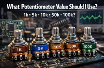
| Pot Value | Main Advantage | Main Drawback | Typical Impression |
|---|---|---|---|
| 1k | Low noise sensitivity, strong drive | Wastes more current | Often too low for general control use |
| 5k | Still robust, less noise-sensitive | Higher current than needed in many circuits | Useful, but not as universal |
| 10k | Balanced current, loading, and noise behavior | Not ideal for every audio or ultra-high impedance case | The common default value |
| 50k | Lower current draw | More sensitive to noise and loading effects | Application-specific |
| 100k | Very low current draw | Can become noisy or unstable in some circuits | Common in some audio or biasing applications |
In other words, 10k is not the theoretical best value for every circuit. It is the value that most often avoids obvious problems on both sides of the tradeoff.
Reason 1: 10k Keeps Current Consumption Reasonable
Whenever a potentiometer is connected across a supply rail as a voltage divider, it draws current continuously. That current is easy to estimate with Ohm’s law:
I = V / R
For a 5V system:
1k Pot
Current ≈ 5V / 1,000Ω = 5mA
10k Pot
Current ≈ 5V / 10,000Ω = 0.5mA
100k Pot
Current ≈ 5V / 100,000Ω = 0.05mA
A 1k potentiometer is often electrically “strong,” but it wastes ten times more current than a 10k version. In battery-powered or high-volume designs, that extra current may be unnecessary. Meanwhile, a 100k potentiometer saves current, but may introduce other problems such as increased noise pickup, slower settling, or poor interaction with the next circuit stage.
A 10k potentiometer reduces this wasted current to a manageable level without drifting too far into high-impedance behavior. That is one major reason it became a default recommendation.
Reason 2: 10k Works Well with Common Analog Inputs
Many potentiometers are used to feed analog signals into microcontrollers, ADCs, comparators, or amplifier stages. In those situations, the source impedance seen by the receiving input matters.
If the potentiometer value is too high, the circuit connected to the wiper may load it down, distort the expected voltage, or make the signal more vulnerable to leakage current and noise. If the value is too low, the circuit works, but you may be burning more current than necessary.
This is why 10k became common in microcontroller education and prototyping. It is an easy value for reading analog positions without creating excessive current draw. Arduino’s official analog input examples and potentiometer basics material use a potentiometer in exactly this kind of variable-voltage role, which helped make 10k a familiar standard among hobbyists and educators.:contentReference[oaicite:1]{index=1}
If your design is based on user-adjustable voltage input, 10k is often a safe starting point because it usually behaves well with general-purpose analog pins and simple divider networks.
When a potentiometer feeds an ADC or analog input, lower source impedance usually improves robustness. A 10k value is commonly chosen because it is low enough for stable readings in many practical systems, without the constant current penalty of much lower values.
Reason 3: 10k Helps Balance Noise and Signal Stability
Higher-resistance circuits are generally more sensitive to parasitic effects. These include:
- electrical noise pickup,
- PCB contamination or leakage,
- input bias current errors,
- long cable effects,
- and stray capacitance.
A 100k potentiometer can work perfectly well in the right design, but it is more likely to behave poorly in a noisy environment or in a casually built prototype. By comparison, a 10k potentiometer is much more forgiving. It produces a lower source impedance at the wiper, which tends to make the signal less fragile.
This matters in real products, where not every environment is clean and not every wiring run is short. The widespread use of 10k is partly a reflection of how forgiving it is in practice.
Reason 4: 10k Is Widely Available Across Mechanical and Digital Families
Another reason 10k is common is simple market reinforcement: manufacturers make it everywhere.
You can find 10k versions in:
- rotary panel potentiometers,
- slide potentiometers,
- trim pots,
- multi-turn precision potentiometers,
- and digital potentiometers.
Once a value becomes common across catalogs, engineers are more likely to design around it because sourcing is easier, second-source options are better, and replacement parts are easier to find years later. That creates a self-reinforcing standard.
For example, digital potentiometer product families from major semiconductor vendors often include 10k options alongside other standard values such as 5k, 50k, and 100k. Microchip’s MCP41HVX1 family includes selectable resistance options including 10k, while TI’s TPL0401B-10-Q1 is specifically a 10-kΩ digital potentiometer.:contentReference[oaicite:2]{index=2}
If you want to browse related IC categories and sourcing paths, see our Data Acquisition section and our manufacturer directory.
Reason 5: 10k Fits Common Design Rules of Thumb
Engineering practice often runs on rules of thumb, especially in early-stage design. One of the most common is this:
If there is no strong reason to choose otherwise, start with a 10k potentiometer for general analog adjustment.
That rule survives because it works often enough. It is suitable for many user controls, sensor thresholds, bias adjustments, and MCU analog interfaces. It is not always optimal, but it is seldom wildly wrong.
That matters in product development. Teams want components that are:
- easy to source,
- easy to simulate,
- easy to prototype with,
- and unlikely to cause surprises.
10k meets that requirement better than many neighboring values.
Why Not Use a Lower Value Like 1k or 2k?
Lower-value potentiometers are absolutely useful, especially when you need a low source impedance or when the next stage strongly loads the wiper. However, they are less common as a general default because of current consumption.
Imagine a product with multiple front-panel controls, all tied across the supply rail. If each control used a 1k potentiometer, the static current draw could become unnecessarily high. That may not matter in a mains-powered rack system, but it definitely matters in battery-powered devices, low-power embedded products, and thermally constrained electronics.
In other words, lower values can be electrically strong but inefficient for many common use cases.
Why Not Use a Higher Value Like 50k or 100k?
Higher-value potentiometers reduce current draw, so at first glance they can look more attractive. But the tradeoff is that the signal at the wiper becomes more sensitive to loading and environmental effects.
Potential drawbacks of higher values include:
- greater susceptibility to noise,
- higher interaction with input bias currents,
- less predictable behavior with long wires,
- more dependence on the input impedance of the next stage,
- and slower RC settling when parasitic capacitance is present.
That does not mean 100k is bad. In many audio, biasing, and low-current applications, 100k may be the right choice. It simply means that 100k is not as universally forgiving as 10k.
Why 10k Is So Common in Arduino and Maker Projects
The popularity of 10k potentiometers exploded further because educational ecosystems adopted them. Beginner electronics kits, Arduino lesson plans, breadboard tutorials, and sensor demos often use potentiometers as adjustable analog voltage sources. Once 10k became the standard in those kits, it became the value that students, makers, and junior engineers recognized first.
That educational momentum matters more than many people realize. The parts engineers learn first often become the parts they continue to trust in prototypes, test fixtures, and early product iterations.
If your audience includes beginners or developers building with popular prototyping ecosystems, a 10k potentiometer also improves documentation clarity because it matches common examples they have already seen. Arduino’s own example ecosystem helped reinforce that familiarity.:contentReference[oaicite:3]{index=3}
Does Taper Matter as Much as Resistance Value?
Yes—sometimes even more.
Many discussions focus only on resistance value, but a potentiometer’s taper is just as important in practical design. A 10k linear potentiometer and a 10k logarithmic potentiometer may have the same nominal resistance, but they feel very different in actual use.
Linear Taper
Resistance changes proportionally with shaft position. Common in control circuits, sensors, and ADC input adjustment.
Logarithmic / Audio Taper
Change is weighted to better match human perception, especially for audio volume control.
So while 10k is a common resistance, the correct taper still depends on the application. For a deeper selection workflow, read our potentiometer selection guide.
Applications Where a 10k Potentiometer Is Often a Good Choice
A 10k potentiometer is often appropriate in the following cases:
Microcontroller Input
Adjusting a voltage into an ADC pin for menus, setpoints, and user controls.
General Analog Adjustment
Setting thresholds, offsets, timing references, and calibration points in moderate-impedance circuits.
User Interface Controls
Brightness, speed, gain, and parameter controls where a simple variable divider is needed.
It is also a common choice for trimmers and calibration controls because it is convenient, available, and usually electrically safe in mixed-signal designs.
When 10k May Not Be the Best Choice
Despite its popularity, 10k should not be treated as an automatic answer. You may want another value if:
| Situation | Better Direction | Why |
|---|---|---|
| Heavy load on the wiper output | Lower value | Reduces loading error and improves drive strength |
| Ultra-low-power battery design | Higher value | Reduces divider current |
| Audio volume control | Depends on taper and circuit | Taper and input/output impedance matter a lot |
| Precision analog front end | Case-specific | Noise, bias current, settling, and tolerance must be analyzed |
| High-voltage or specialized digital potentiometer design | Part-family dependent | Available resistance values vary by manufacturer and device type |
This is exactly why engineers should start with application requirements—not with habit alone.
How Engineers Usually Decide Between 10k, 50k, and 100k
A simple practical method is to ask four questions:
1. How much current can I afford to waste?
If current draw matters, avoid unnecessarily low values.
2. How sensitive is the next stage to source impedance?
If the wiper feeds a sensitive or loading-prone input, avoid going too high.
3. Is the environment electrically noisy?
Noisy layouts and long wires usually favor lower impedance.
4. Is this a human-interface or signal-conditioning function?
User controls can tolerate many values, but signal circuits may require closer analysis.
When those answers are not extreme in either direction, 10k often wins by default.
Supply Chain and Standardization Also Matter
Component popularity is not driven by electrical theory alone. It is also shaped by:
- catalog standardization,
- OEM design habits,
- educational kits,
- second-source availability,
- and long-term replacement convenience.
Because 10k is stocked so widely, engineers can specify it with confidence in both prototype and production workflows. This is especially relevant for distributors and sourcing teams, where the most common value is often the easiest one to buy in multiple form factors and brands.
You can also explore brand availability through our manufacturers directory and selected vendor pages such as Texas Instruments.
10k in Mechanical Potentiometers vs Digital Potentiometers
It is worth noting that the “10k is common” pattern appears in both mechanical and digital forms.
In a mechanical potentiometer, 10k often appears in panel controls, rotary knobs, and slide interfaces. In a digital potentiometer, 10k is also common because it provides a useful compromise between terminal current capability, bandwidth, and typical signal-conditioning use cases. Semiconductor vendors frequently offer 10k as one of the standard resistance options in a product family.:contentReference[oaicite:4]{index=4}
If your design may move from a manual control to a programmable one, 10k can be a convenient bridging value because both product types often exist in that range.
Common Misunderstandings About 10k Potentiometers
Misunderstanding 1: 10k is always correct
No. It is common because it is versatile, not because it is universally optimal.
Misunderstanding 2: Lower resistance is always better
No. Lower resistance improves drive strength but increases current draw.
Misunderstanding 3: Higher resistance always saves power with no downside
No. Higher resistance can increase sensitivity to loading, noise, and parasitics.
Misunderstanding 4: Pot value matters more than taper
No. In many user controls, taper strongly affects the actual feel and usability.
Final Answer: Why Is 10k Potentiometer So Common?
A 10k potentiometer is so common because it provides a highly practical compromise. It is low enough to produce stable, usable analog control in many circuits, but high enough to avoid wasting excessive current. It works well in common voltage-divider applications, matches the needs of many microcontroller and analog input designs, is less fragile than higher-value options in noisy real-world conditions, and is widely available across product families.
In short, 10k became common because it is the value that most often works well without causing trouble.
That is why engineers keep using it, educators keep teaching it, and manufacturers keep stocking it.
The Complete Guide to Potentiometers
Start here if you want a broader overview of potentiometer structure, types, and working principles.
How to Choose the Right Potentiometer
Use this guide when selecting resistance value, taper, power rating, mounting style, and lifetime.
Linear vs Rotary Potentiometers
Compare the two most common form factors and see which one fits your application better.
Data Acquisition Components
Browse related analog and interface categories for adjustable signal-conditioning designs.
FAQ
Is a 10k potentiometer always the best choice?
No. It is a strong default for many general-purpose analog applications, but the best value still depends on current draw, source impedance, circuit loading, taper, and environmental noise.
Why is 10k common in Arduino projects?
Because it gives a useful balance between current consumption and stable analog readings. It is low enough to work well in many simple ADC input circuits, but not so low that it wastes unnecessary current.
Is 10k better than 100k for a potentiometer?
Not always. A 10k potentiometer is often more robust against loading and noise, while a 100k potentiometer draws less current. The right choice depends on the design goal and the impedance of the surrounding circuit.
Does potentiometer taper matter more than resistance?
In many user-interface applications, taper matters just as much as resistance. For example, audio controls often depend heavily on logarithmic taper for natural adjustment feel.
Can I replace a 10k potentiometer with another value?
Sometimes, but not automatically. A replacement with a much lower or higher resistance may change current draw, output behavior, loading, control feel, and overall circuit performance.