If you’ve ever cracked open an ESP8266 dev board, an Arduino-compatible module, or a low-power gadget and spotted a flat SOT-223 package labeled “1117,” you’re looking at one of the most ubiquitous LDOs in hobbyist and production hardware alike: the AMS1117. This article is a thorough, design-first dive into what the AMS1117 really is, how it behaves electrically and thermally, how to make it stable (and keep it that way), and when you should pick something else.
We’ll cover pinouts, packages, the adjustable version math, capacitor choices (including the notorious ESR caveat), dropout behavior, layout tips, thermal headroom, and common pitfalls—plus quick comparisons to close cousins like the LM1117 and modern replacements.
AMS1117 Voltage Regulator Overview
The AMS1117 family is a three-terminal low-dropout (LDO) linear voltage regulator available in several fixed outputs (1.2 V, 1.5 V, 1.8 V, 2.5 V, 2.85 V, 3.3 V, 5.0 V) and an adjustable version. Its hallmark is simplicity: a single device plus a couple of capacitors turns a higher, somewhat noisy supply into a clean rail. It includes current limit and thermal shutdown. Depending on the datasheet source, it is rated “up to 1 A” of output current, with dropout typically around 1.1–1.3 V at high load.
The AMS1117 is not a high-efficiency converter. Being linear, it burns the voltage difference as heat. That’s fine at modest currents or small Vin–Vout deltas; it’s a thermal headache otherwise. (We’ll quantify that shortly.)
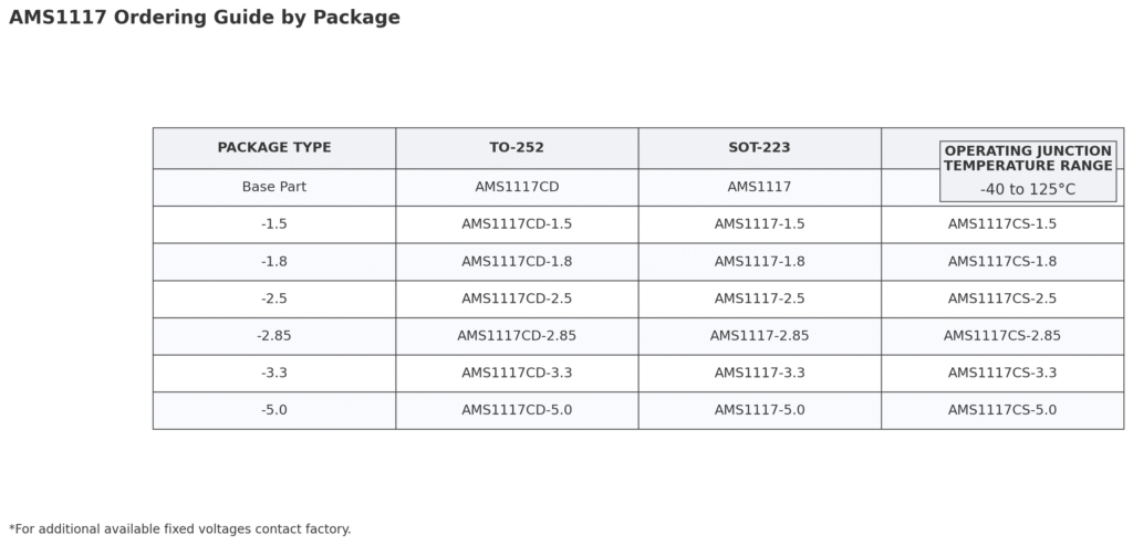
Popular AMS1117 Regulator IC Parts (Fixed & Adjustable)
What’s common across all variants
- Package/Pin: most often SOT-223 (back tab = VOUT), also TO-252/DPAK and some SO-8.
- Output current: up to ~0.8–1.0 A (thermally limited).
- Dropout (near max load): ~1.1–1.3 V. Less at lighter loads.
- Stability: prefers ~22 µF with some ESR at VOUT (classic choice: tantalum). If you use all-ceramic, ensure effective ESR (e.g., add small R or parallel an electrolytic).
- Typical caps that “just work”: VIN 10 µF + 0.1 µF, VOUT 22 µF + 0.1 µF, placed tight.
- Minimum load: some lots/“1117” families regulate best with ≥5–10 mA bleed.
- Thermal: power = (VIN−VOUT)×I(V_{IN}-V_{OUT}) \times I(VIN−VOUT)×I. Give the VOUT tab generous copper.
Fixed-Voltage Parts
AMS1117-1.2
Ultra-low rail for legacy cores and precision analog biasing; great when you need tight headroom above bandgap but can tolerate modest load transients.
- Nominal VOUT: 1.2 V
- Uses: Core rails for old low-power ASICs/PLDs, precision references (with post filtering), analog biasing.
- Notes: Little headroom to the 1.25 V reference—watch tolerance and load step.
AMS1117-1.5
A “gentle” low-voltage rail often used in older DSP/FPGA islands; balances noise margin vs. dynamic range when 1.2 V is too low and 1.8 V is too high.
- Nominal VOUT: 1.5 V
- Uses: Legacy DSP/FPGA cores, audio/analog front ends that like 1.5 V.
- Notes: Often chosen when 1.2 V is too low but 1.8 V is too high for noise/PSRR margins.
AMS1117-1.8
Modern low-core favorite; feeds MCUs, sensors, and digital cores that like 1.8 V. Watch dropout if VIN is near 3.0 V at higher loads.
- Nominal VOUT: 1.8 V
- Uses: DDR/LPDDR I/O islands (light current), sensors, low-voltage logic.
- Notes: Very common “core” rail. Check dropout if VIN is only ~3.0 V.
AMS1117-2.5
Mixed-signal comfort zone; popular for ADC/DAC analog domains and legacy memories where 3.3 V is noisy/overkill but 1.x V is too tight.
- Nominal VOUT: 2.5 V
- Uses: Older memory, ADC/DAC analog domains, mixed-signal islands.
- Notes: Good middle ground when 3.3 V is too high for noise or headroom.
AMS1117-2.85
Niche but purposeful; hits flash/RF parts that spec 2.85 V exactly. Chosen to satisfy datasheets and avoid over-voltage margins.
- Nominal VOUT: 2.85 V
- Uses: Certain RF/analog blocks and flash memories that spec 2.85 V.
- Notes: Picked for BOM compatibility where exact 2.85 V is required by datasheet.
AMS1117-3.3 (most common)
The everyday workhorse for 5 V → 3.3 V rails (ESP8266/ESP32, sensors). Simple, predictable, and cheap—just mind thermals above ~200–300 mA.
- Nominal VOUT: 3.3 V
- Uses: MCUs/SoCs/wireless modules (ESP8266/ESP32), sensors, logic rails from 5 V USB.
- Notes: Classic 5→3.3 V linear stage—great for ≤200–300 mA continuous. At higher current, check thermals.
AMS1117-5.0
Clean 5 V from 7–12 V adapters or as a post-reg after a buck. Excellent for small analog loads; inefficient for big drops at high current.
- Nominal VOUT: 5.0 V
- Uses: Clean 5 V analog/logic rail from 7–12 V adapters, post-reg after buck.
- Notes: Efficiency is poor if dropping from 12 V at high current—use a buck pre-reg.
Adjustable Part
AMS1117-ADJ (adjustable, 1.25 V ref)
Your flexible tool: set any rail with a resistor divider; add an ADJ-to-GND cap to boost PSRR. Perfect for 2.8 V RF rails or battery-derived 3.3 V.
- Range: ~1.25 V up to (VIN – dropout)
- Set formula: VOUT≈1.25×(1+R2/R1)+IADJ⋅R2V_{OUT} \approx 1.25 \times (1 + R2/R1) + I_{ADJ}\cdot R2VOUT≈1.25×(1+R2/R1)+IADJ⋅R2
- Uses: Custom rails (e.g., 2.8 V for RF, 4.2→3.3 V from Li-ion), lab/proto flexibility.
- Notes: A small cap from ADJ→GND boosts PSRR (then keep VOUT cap at the recommended value). Choose R1 ≈ 120–240 Ω to keep divider current >> I_ADJ.
Common Manufacturers & Close “1117-Compatible” Families
Below is a practical, engineering-focused buyer’s guide to the most common “1117-class” regulators and the manufacturer companies behind them. All are broadly similar to the AMS1117, but each family has its own quirks around dropout, stability/ESR, accuracy, quiescent current, packages, and thermals. Always validate with the exact datasheet for the part you’ll buy.
These are widely used, footprint/behavior-compatible (always verify pinout, dropout, ESR rules, and max current in each datasheet):
- Advanced Monolithic Systems (AMS) — the namesake AMS1117 family.
- Texas Instruments — LM1117 (800 mA class). Clear ESR guidance; often used as a drop-in.
- Analog Devices (ex-Linear Technology) — LT1117 family (robust, well-documented).
- onsemi — NCP1117 series (multiple fixed voltages + adjustable).
- STMicroelectronics — LD1117 series (popular, many fixed options).
- Diodes Incorporated — AZ1117 / AZ1117C variants (SOT-223 / DPAK options).
Related/alternative LDOs (not always drop-in):
- TI TLV1117/TLV1117-xx, LP5907, TPS7xx families (many are ceramic-stable, lower Iq, different limits).
- Microchip MCP17xx/MCP18xx families (lower Iq options; check pinout/ESR requirements).
- onsemi NCV/NCP low-Iq LDO lines for automotive/industrial.
Tip: If you’re standardizing a design, keep a “1117-class” dual-source plan (e.g., LM1117 + LD1117) and validate with your exact capacitors and PCB layout—most field issues come from cap ESR/layout or thermals, not the silicon itself.
Advanced Monolithic Systems (AMS) — AMS1117
Positioning: The namesake, most widespread in hobby/ODM boards (ESP8266/ESP32, Arduino clones).
Outputs: Fixed 1.2/1.5/1.8/2.5/2.85/3.3/5.0 V + Adjustable (1.25 V ref).
Current & Dropout: Marketed up to ~1 A; practical thermal limit in SOT-223 is often lower. Typical dropout ≈ 1.1–1.3 V near high load.
Stability: Classic guidance expects some ESR at VOUT (e.g., ~22 µF tantalum). All-ceramic BOMs can oscillate unless ESR is added or paralleled with an electrolytic.
Quiescent current: mA-class (varies by lot/datasheet revision).
Packages: SOT-223 (tab = VOUT), TO-252/DPAK, some SO-8 variants exist in the market.
Pros: Ubiquitous, inexpensive, easy to source; reference designs abound.
Watch-outs: Quality and limits vary across foundries/clones; design to thermal not label current; verify minimum-load requirements.
Texas Instruments — LM1117
Positioning: Often the “gold standard” reference for 1117 behavior; widely treated as a drop-in for AMS1117 footprints.
Outputs: Similar fixed set + adjustable.
Current & Dropout: 800 mA class device; dropout around ~1.2 V near max load.
Stability: TI’s datasheet is explicit about minimum ESR for the output capacitor (ceramic-only requires special care). Great as a baseline for stability rules.
Accuracy & Temp: Fixed options typically ±1–2%; −40 to +125 °C grades available.
Packages: SOT-223, TO-220, TO-252, etc.
Pros: Clear documentation, predictable across lots; excellent for “works-first-time” designs.
Watch-outs: Treat 800 mA as an electrical limit—board copper still governs thermals.
Analog Devices (ex-Linear Technology) — LT1117
Positioning: High documentation quality; solid electrical behavior; often used in industrial gear.
Outputs: Common fixed rails + adjustable.
Current & Dropout: Similar to LM/AMS class; expect ~1.1–1.3 V dropout near high load depending on variant.
Stability: Good guidance in datasheet; still expects appropriate ESR or mixed cap types for robust phase margin.
Noise/PSRR: Generally well-characterized; adjustable version with ADJ bypass cap gives useful PSRR.
Packages: SOT-223, TO-220, others.
Pros: Robust silicon, conservative specs; strong app notes/history.
Watch-outs: Unit pricing may be higher than commodity AMS/clone parts.
Onsemi — NCP1117 Series
Positioning: Workhorse 1117 family with automotive/industrial variants in the broader NCP/NCV lines.
Outputs: Fixed + adjustable.
Current & Dropout: In the familiar 800 mA-to-1 A class; similar dropout profile.
Stability: Datasheets usually provide ESR windows and example cap types; ceramic-only still needs attention.
Packages: SOT-223, DPAK/TO-252, TO-220.
Pros: Good supply chain breadth, long-term availability, AEC-Q options in related lines.
Watch-outs: Confirm pinout equivalence (tab = VOUT) and ESR requirements per exact suffix.
STMicroelectronics — LD1117 Series
Positioning: Very common in EU supply chains; popular on dev boards and industrial modules.
Outputs: Standard fixed rails + adjustable.
Current & Dropout: Similar class; dropout typically around 1.1–1.2 V at high load (check the exact code).
Stability: ST docs clearly call for output cap ESR ranges; designs with only MLCCs should include an electrolytic/tantalum or small series R.
Packages: SOT-223, DPAK, TO-220, etc.
Pros: Widely second-sourced; consistent documentation; good for dual-sourcing with LM1117.
Watch-outs: Several suffixes/temperature grades—match your target environment.
Diodes Incorporated — AZ1117 / AZ1117C
Positioning: Cost-effective, broad distribution; versions tailored to different tolerances and packages.
Outputs: Fixed + adjustable; multiple trim options.
Current & Dropout: In the same neighborhood as peers; verify max IOUT and dropout per part number.
Stability: Datasheet guidance typically includes ESR ranges; some “C” suffixes indicate tightened specs.
Packages: SOT-223, DPAK/TO-252, TO-220.
Pros: Competitive price/performance; good availability in Asia/EU channels.
Watch-outs: Ensure the exact capacitor type and ESR you plan is compatible with the chosen suffix.
Key Features of AMS1117 LDO Regulator ICs
- Output current: up to ~0.8–1.0 A (thermally limited; board copper matters).
- Low dropout: ~1.1–1.3 V near max load (less at lighter loads).
- Accuracy: typically ±1–2% for fixed versions (vendor dependent).
- Protections: internal current limit and thermal shutdown.
- Stability needs: sensitive to output capacitor ESR; classic recommendation ~22 µF tantalum (or ensure effective ESR if using ceramics).
- PSRR tweak: adding a small capacitor from ADJ to GND (adjustable version) improves ripple rejection.
- Quiescent current: in the mA range (varies by vendor/revision).
- Operating temp: commonly −40 °C to +125 °C (check datasheet).
AMS1117 Voltage Regualtor Applications
- 5 V → 3.3 V rails for MCUs/SoCs/wireless modules (ESP8266/ESP32, Arduino-class boards)
- Post-regulation after a buck to reduce ripple for analog/RF or sensitive mixed-signal domains
- Peripheral rails for sensors, memory, small digital/analog loads
- Prototyping and education boards where low BOM count and simplicity matter
- Battery-powered light-load rails (e.g., 4.2 V Li-ion → 3.3 V), with attention to efficiency and thermals
AMS1117 Pinout
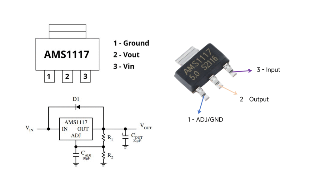
Default package: SOT-223 (front view)
- GND/ADJ — GND on fixed-voltage versions; ADJ (feedback) on adjustable
- VOUT — Regulated output
- VIN — Input supply
Tab (back metal pad): VOUT (electrically tied to pin 2)
Important: In SOT-223 and most DPAK/TO-252 variants, the tab is VOUT, not GND. Any heatsinking copper under the tab must connect to VOUT, otherwise you’ll short the regulator.
Common packages: SOT-223 (most popular), TO-252/DPAK (better thermals), and some SO-8/exposed-pad variants (check each datasheet for exact pin/pad mapping).
Pin Configuration
| Pin Number | Pin Name | Description |
| 1 | Adjust/Ground | This pins adjusts the output voltage, if it is a fixed voltage regulator it acts as ground |
| 2 | Output Voltage (Vout) | The regulated output voltage set by the adjust pin can be obtained from this pin |
| 3 | Input Voltage (Vin) | The input voltage which has to be regulated is given to this pin |
AMS1117 Datasheet (Snapshot)
Overview
AMS1117 is a low-dropout (LDO) linear regulator available in fixed outputs (1.2/1.5/1.8/2.5/2.85/3.3/5.0 V) and an adjustable version (1.25 V reference). It integrates current limiting and thermal shutdown, offering simple, dependable regulation for digital and mixed-signal systems. (from AMS1117 Datasheet).
Key Electricals (typical, family-level)
- Output current: up to ~0.8–1.0 A (thermally limited; board copper matters)
- Dropout voltage: ~1.1–1.3 V near high load (smaller at lighter loads)
- Accuracy (fixed): typically ±1–2% (vendor/suffix dependent)
- Quiescent current: mA class (varies by source)
- Operating temperature: commonly −40 °C to +125 °C (verify your exact part)
- Stability: loop expects some ESR at VOUT; the classic, robust choice is ≈22 µF tantalum (or add effective ESR when using all-ceramic outputs)
Recommended External Components
- VIN: ~10 µF bulk (electrolytic/tantalum) + 0.1 µF ceramic, placed tight to VIN–GND
- VOUT: ≈22 µF (tantalum/electrolytic with suitable ESR) + 0.1 µF ceramic, placed tight to VOUT–GND
- Adjustable version: VOUT≈1.25×(1+R2R1)+IADJ⋅R2V_{OUT} \approx 1.25 \times \left(1+\frac{R_2}{R_1}\right) + I_{ADJ}\cdot R_2VOUT≈1.25×(1+R1R2)+IADJ⋅R2 Use R1 ≈ 120–240 Ω, pick R2 for target VOUT, and optionally add a small ADJ-to-GND capacitor to improve PSRR (keep output cap per stability guidance).
Thermal Design
- Power dissipation: P=(VIN−VOUT)×IOUTP = (V_{IN} – V_{OUT}) \times I_{OUT}P=(VIN−VOUT)×IOUT
- SOT-223 needs a generous VOUT copper pour (tab = VOUT) and via stitching for heat spreading.
- For large ΔV × I (e.g., 12 → 3.3 V at hundreds of mA), consider a buck pre-regulator feeding the LDO.
Common Ordering Options
- Fixed: AMS1117-1.2 / -1.5 / -1.8 / -2.5 / -2.85 / -3.3 / -5.0
- Adjustable: AMS1117-ADJ
- Close, “1117-compatible” families (verify pinout/ESR rules): TI LM1117, ADI LT1117, ST LD1117, onsemi NCP1117, Diodes AZ1117.
Conclusion
The AMS1117 is a widely used 3-pin SMD low-dropout (LDO) regulator offered in multiple fixed-voltage options and an adjustable version. It can supply up to about 1 A (thermally limited), with selectable outputs typically from 1.5 V to 5.0 V. At high load, it features a low dropout of roughly 1.3 V, making it a simple, dependable choice for generating clean rails in compact designs.
- Simple, cheap LDO for small Vin–Vout differences and moderate current.
- Needs ESR: put 22 µF tantalum at VOUT (plus small ceramic).
- Dropout ≈ 1.2–1.3 V at high load; budget headroom accordingly.
- Thermal is king: compute PPP, check θJA ~136 °C/W (SOT-223 example), and pour copper on VOUT tab.
- For big drops or higher current, use a buck (or a newer LDO).
FAQ About AMS1117 Regulator ICs
1) What is the AMS1117?
The AMS1117 is a three-terminal low-dropout (LDO) linear regulator available in several fixed outputs (1.2–5.0 V) and an adjustable version. It integrates current limit and thermal shutdown and can supply up to ~0.8–1.0 A (thermally limited).
2) What is AMS1117-3.3?
AMS1117-3.3 is the fixed 3.3 V variant. It’s widely used on dev boards (ESP8266/ESP32, Arduino clones) to derive a clean 3.3 V rail from a 5 V source.
3) How does the AMS1117 work?
It regulates using a 1.25 V bandgap reference.
- Fixed versions use internal resistors to set VOUT.
- Adjustable version sets VOUT with an external divider:
VOUT≈1.25×(1+R2/R1)+IADJ⋅R2V_{OUT} \approx 1.25 \times (1 + R_2/R_1) + I_{ADJ}\cdot R_2VOUT≈1.25×(1+R2/R1)+IADJ⋅R2.
4) What is the dropout voltage?
Typical dropout near high load is ~1.1–1.3 V (lower at lighter loads). For 3.3 V out at heavy load, plan for ≥4.5–4.7 V at VIN.
5) Can it convert 5 V to 3.3 V?
Yes. 5 V → 3.3 V is a classic use case. At 200–300 mA continuous it’s usually fine; at higher currents, power dissipation rises and you may hit thermal limits without large copper or a heatsink.
6) What current can it deliver?
Electrically, many 1117-class parts are rated up to ~0.8–1.0 A. In practice, the thermal budget of your PCB (especially with SOT-223) is the limiter. Always compute P=(VIN−VOUT)×IP = (V_{IN}-V_{OUT})\times IP=(VIN−VOUT)×I and check temperature rise.
7) What capacitors does it need?
The control loop expects some ESR on the output capacitor. A robust recipe is:
- VIN: ~10 µF bulk + 0.1 µF ceramic (close to pins)
- VOUT: ~22 µF (tantalum/electrolytic with ESR in range) + 0.1 µF ceramic
If using ceramics only, add a small series R or parallel an electrolytic/tantalum to ensure stability.
8) What’s special about the package tab?
In SOT-223 and DPAK/TO-252, the back tab = VOUT (not GND). Pour copper on VOUT under the tab for heatsinking; never tie it to ground.
9) Does it need a minimum load?
Some versions regulate best with a few mA minimum load (often ~5–10 mA). If your load can drop near zero, add a small bleeder resistor.
10) Is the AMS1117 “high efficiency”?
No—like all linear regulators, efficiency ≈ VOUT/VINV_{OUT}/V_{IN}VOUT/VIN. For large voltage drops and higher currents, use a buck converter (optionally followed by the AMS1117 for noise cleanup).
11) Can I use it as a battery charger?
Not directly. It lacks constant-current/constant-voltage charging control and safety features needed for Li-ion. Use a dedicated charger IC.
12) What are common alternatives to AMS1117?
Close, footprint-compatible families: LM1117 (TI), LT1117 (ADI), LD1117 (ST), NCP1117 (onsemi), AZ1117 (Diodes). For ceramic-stable/low-Iq or better efficiency, consider newer LDOs (e.g., TLV/TPS families) or a buck.
13) What packages are available for AMS1117 LDO Regulator?
Commonly SOT-223 (most dev boards), TO-252/DPAK (better thermals), and some SO-8/exposed-pad variants (verify pad mapping in the specific datasheet).


