Microcontrollers like the Arduino are powerful, but their number of I/O pins is limited. If you want to control dozens of LEDs, 7-segment displays, or other output devices, you’ll quickly run out of pins. That’s where the 74HC595 shift register comes in. This tiny IC converts serial data into parallel outputs, allowing you to control 8 outputs with just 3 Arduino pins. By chaining multiple chips together, you can expand almost infinitely — without overloading your microcontroller.
The 74HC595 from Texas Instruments is a high-performance 8-bit shift register/latch that turns a microcontroller’s serial data into reliable parallel outputs. Built on silicon-gate C2MOS technology, the 74HC595 delivers low power consumption, high noise immunity, and stable operation—ideal for space-constrained designs. With only three control lines (data, clock, latch), the 74HC595 IC lets Arduino and other MCUs drive eight latched outputs, keeping displays, LEDs, and indicators crisp and synchronized. Need more I/O? Simply daisy-chain additional 74HC595 devices via QH′ to DS and scale in tidy blocks of eight, updating every output with a single latch pulse. If you’re optimizing layout, reducing wiring, or chasing efficiency, the 74HC595 provides a compact, robust path to serial-to-parallel expansion.
In this guide, you’ll learn:
-
What the 74HC595 is and how it works
-
Its pinout and datasheet specs
-
How to wire and use it with Arduino
-
Common applications and advanced tricks
What is the TI 74HC595 Shift Register?
The 74HC595 is an 8-bit Serial-In Parallel-Out (SIPO) shift register.
The Texas Instruments 74HC595 is an 8-bit Serial-In Parallel-Out (SIPO) shift register, widely used for expanding the number of outputs on microcontrollers. In simple terms, it takes data sent one bit at a time through a single pin and stores it internally. Once a full 8-bit sequence is shifted in, the chip can present those bits simultaneously on its eight output pins, labeled Q0–Q7.
This design is built around three main functional blocks:
-
Shift Register – receives serial input data, one bit per clock pulse.
-
Storage Register – holds the shifted data and prevents output flicker while new bits are being clocked in.
-
Tri-State Outputs – provide flexibility to share output lines with other devices on a common bus.
The dual-register architecture is what makes the 74HC595 so reliable in display and control applications. You can load new data into the shift register in the background, then update all outputs in a single latch pulse—ensuring crisp, synchronized changes.
TI’s 74HC595 family also comes in different packages to suit your design needs. For compact, surface-mounted applications, there’s the 74HC595 in an SOIC package. For breadboard-friendly prototyping, the SN74HC595N in a DIP-16 package is often preferred. Both function the same way, but the choice of package depends on whether you’re building a quick prototype or a production-ready PCB.
In practice, the 74HC595 makes it easy to control LEDs, 7-segment displays, and other output devices with just three microcontroller pins, making it a staple component in both hobbyist and professional electronics projects.
TI 74HC595 Family – Package & Ordering Guide
To help you choose the right 74HC595 for prototyping or production, here’s a consolidated table of common TI/legacy-TI part numbers, their packages, temperature grades, and typical orderable forms. Use it to match footprint (SOIC/TSSOP/SSOP/DIP/QFN), operating temperature, and packaging (Tube / Cut Tape / Tape & Reel) to your build and manufacturing flow.
Tip: For breadboards choose PDIP; for compact PCBs pick SOIC/TSSOP/SSOP; for highest density consider QFN. “E4/G4/G3” suffixes typically denote lead-free/green variants; “R” often indicates Tape & Reel.
| Part Number | Description | Orderable / Packaging | Function | Temp Range | Mounting | Package & Width | Package Code | Notes / Status |
|---|---|---|---|---|---|---|---|---|
| SN74HC595DBR | IC SR TRI-STATE 8BIT 16-SSOP | Tape & Reel (TR) | Serial to Parallel, Serial | -40°C ~ 85°C | Surface Mount | 16-SSOP (0.209″, 5.30mm) | 16-SSOP | — |
| SN74HC595ADBR | IC SR TRI-STATE 8BIT 16-SSOP | Tape & Reel (TR) | Serial to Parallel, Serial | -40°C ~ 85°C | Surface Mount | 16-SSOP (0.209″, 5.30mm) | 16-SSOP | — |
| CD74HC595SM96 | IC SR TRI-STATE 8BIT 16-SSOP | Tape & Reel (TR) | Serial to Parallel, Serial | -55°C ~ 125°C | Surface Mount | 16-SSOP (0.209″, 5.30mm) | 16-SSOP | Extended temp |
| SN74HC595DBRE4 | IC SR TRI-STATE 8BIT 16-SSOP | — | Serial to Parallel, Serial | -40°C ~ 85°C | Surface Mount | 16-SSOP (0.209″, 5.30mm) | 16-SSOP | Lead-free/green variant |
| SN74HC595DBRG4 | IC SR TRI-STATE 8BIT 16-SSOP | — | Serial to Parallel, Serial | -40°C ~ 85°C | Surface Mount | 16-SSOP (0.209″, 5.30mm) | 16-SSOP | Lead-free/green variant |
| SN74HC595ADB | IC SR TRI-STATE 8BIT 16-SSOP | — | Serial to Parallel, Serial | -40°C ~ 85°C | Surface Mount | 16-SSOP (0.209″, 5.30mm) | 16-SSOP | — |
| CD74HC595NS | IC SHFT REG TRI-STATE 8BIT 16-SO | Bulk | — | — | Surface Mount | 16-SOIC (0.209″, 5.30mm) | 16-SO | — |
| CD74HC595NSE4 | IC SHFT REG TRI-STATE 8BIT 16-SO | Tape & Reel (TR) | — | — | Surface Mount | 16-SOIC (0.209″, 5.30mm) | 16-SO | Lead-free |
| CD74HC595NSG4 | IC SHFT REG TRI-STATE 8BIT 16-SO | Tube | — | — | Surface Mount | 16-SOIC (0.209″, 5.30mm) | 16-SO | Lead-free |
| CD74HC595NSR | IC SHFT REG TRI-STATE 8BIT 16-SO | Tape & Reel (TR), Cut Tape (CT) | — | — | Surface Mount | 16-SOIC (0.209″, 5.30mm) | 16-SO | — |
| SN74HC595BRWNR | IC SR TRI-STATE 8BIT 16-X1QFN | Tape & Reel (TR) | Serial to Parallel | -55°C ~ 125°C | Surface Mount | 16-X1QFN (2.5×2.5, EP) | 16-XFQFN | Very compact |
| SN74HC595ANS | IC SHFT REG TRI-STATE 8BIT 16-SO | — | Serial to Parallel, Serial | -40°C ~ 85°C | Surface Mount | 16-SOIC (0.209″, 5.30mm) | 16-SO | — |
| SN74HC595DWR | IC SR TRI-STATE 8BIT 16-SOIC | Cut Tape (CT) | Serial to Parallel, Serial | -40°C ~ 85°C | Surface Mount | 16-SOIC (0.295″, 7.50mm) | 16-SOIC | Wide body |
| SN74HC595DW | IC SR TRI-STATE 8BIT 16-SOIC | Tube | Serial to Parallel, Serial | -40°C ~ 85°C | Surface Mount | 16-SOIC (0.295″, 7.50mm) | 16-SOIC | Wide body |
| CD74HC595DW | IC SR TRI-STATE 8BIT 16-SOIC | Tube | Serial to Parallel, Serial | -55°C ~ 125°C | Surface Mount | 16-SOIC (0.295″, 7.50mm) | 16-SOIC | Extended temp |
| CD74HC595DWR | IC SR TRI-STATE 8BIT 16-SOIC | Cut Tape (CT) | Serial to Parallel, Serial | -55°C ~ 125°C | Surface Mount | 16-SOIC (0.295″, 7.50mm) | 16-SOIC | Extended temp |
| SN74HC595DWRE4 | IC SR TRI-STATE 8BIT 16-SOIC | Tape & Reel (TR) | — | — | Surface Mount | 16-SOIC (0.295″, 7.50mm) | 16-SOIC | Lead-free |
| SN74HC595DWRG4 | IC SR TRI-STATE 8BIT 16-SOIC | Tape & Reel (TR) | — | — | Surface Mount | 16-SOIC (0.295″, 7.50mm) | 16-SOIC | Lead-free |
| SN74HC595NSR | IC SHFT REG TRI-STATE 8BIT 16-SO | Tape & Reel (TR) | Serial to Parallel, Serial | -40°C ~ 85°C | Surface Mount | 16-SOIC (0.209″, 5.30mm) | 16-SO | Narrow body |
| SN74HC595ANSR | IC SHFT REG TRI-STATE 8BIT 16-SO | Cut Tape (CT) | Serial to Parallel, Serial | -40°C ~ 85°C | Surface Mount | 16-SOIC (0.209″, 5.30mm) | 16-SO | Narrow body |
| SN74HC595ANSRE4 | IC SHFT REG TRI-STATE 8BIT 16-SO | — | Serial to Parallel, Serial | -40°C ~ 85°C | Surface Mount | 16-SOIC (0.209″, 5.30mm) | 16-SO | Lead-free |
| SN74HC595DR | IC SR TRI-STATE 8BIT 16-SOIC | Tape & Reel (TR) | Serial to Parallel, Serial | -40°C ~ 85°C | Surface Mount | 16-SOIC (0.154″, 3.90mm) | 16-SOIC | Narrow body |
| CD74HC595M96 | IC SR TRI-STATE 8BIT 16-SOIC | Tape & Reel (TR) | Serial to Parallel, Serial | -55°C ~ 125°C | Surface Mount | 16-SOIC (0.154″, 3.90mm) | 16-SOIC | Extended temp |
| SN74HC595DRG3 | IC SR TRI-STATE 8BIT 16-SOIC | Tape & Reel (TR) | Serial to Parallel, Serial | -40°C ~ 85°C | Surface Mount | 16-SOIC (0.154″, 3.90mm) | 16-SOIC | Lead-free |
| CD74HC595M | IC SR TRI-STATE 8BIT 16-SOIC | Tube | Serial to Parallel, Serial | -55°C ~ 125°C | Surface Mount | 16-SOIC (0.154″, 3.90mm) | 16-SOIC | Extended temp |
| SN74HC595DRE4 | IC SR TRI-STATE 8BIT 16-SOIC | — | Serial to Parallel, Serial | -40°C ~ 85°C | Surface Mount | 16-SOIC (0.154″, 3.90mm) | 16-SOIC | Lead-free |
| SN74HC595DRG4 | IC SR TRI-STATE 8BIT 16-SOIC | Tape & Reel (TR) | — | — | Surface Mount | 16-SOIC (0.154″, 3.90mm) | 16-SOIC | Lead-free |
| SN74HC595DE4 | IC SR TRI-STATE 8BIT 16-SOIC | Tube | — | — | Surface Mount | 16-SOIC (0.154″, 3.90mm) | 16-SOIC | Lead-free |
| SN74HC595DG4 | IC SR TRI-STATE 8BIT 16-SOIC | Tube | — | — | Surface Mount | 16-SOIC (0.154″, 3.90mm) | 16-SOIC | Lead-free |
| CD74HC595MT | IC SR TRI-STATE 8BIT 16-SOIC | Tape & Reel (TR), Cut Tape (CT) | — | — | Surface Mount | 16-SOIC (0.154″, 3.90mm) | 16-SOIC | — |
| SN74HC595D | IC SR TRI-STATE 8BIT 16-SOIC | Tube | — | — | Surface Mount | 16-SOIC (0.154″, 3.90mm) | 16-SOIC | Obsolete |
| SN74HC595DT | IC SR TRI-STATE 8BIT 16-SOIC | Tape & Reel (TR), Cut Tape (CT) | — | — | Surface Mount | 16-SOIC (0.154″, 3.90mm) | 16-SOIC | Obsolete |
| SN74HC595N | IC SR TRI-STATE 8BIT 16-PDIP | — | Serial to Parallel, Serial | -40°C ~ 85°C | Through Hole | 16-DIP (0.300″, 7.62mm) | 16-PDIP | Breadboard-friendly |
| CD74HC595E | IC SR TRI-STATE 8BIT 16-PDIP | Tube | Serial to Parallel, Serial | -55°C ~ 125°C | Through Hole | 16-DIP (0.300″, 7.62mm) | 16-PDIP | Extended temp |
| SN74HC595NE4 | IC SR TRI-STATE 8BIT 16-PDIP | Tube | — | — | Through Hole | 16-DIP (0.300″, 7.62mm) | 16-PDIP | Lead-free |
| CD74HC595EG4 | IC SR TRI-STATE 8BIT 16-PDIP | Tube | — | — | Through Hole | 16-DIP (0.300″, 7.62mm) | 16-PDIP | Lead-free |
| SN74HC595PWR | IC SR TRI-STATE 8BIT 16-TSSOP | Tape & Reel (TR) | Serial to Parallel, Serial | -40°C ~ 85°C | Surface Mount | 16-TSSOP (0.173″, 4.40mm) | 16-TSSOP | Narrow body |
| SN74HC595MPWREP | IC SR TRI-STATE 8BIT 16-TSSOP | Tape & Reel (TR) | Serial to Parallel, Serial | -55°C ~ 125°C | Surface Mount | 16-TSSOP (0.173″, 4.40mm) | 16-TSSOP | Enhanced rel. / ext. temp |
| SN74HC595PWRE4 | IC SR TRI-STATE 8BIT 16-TSSOP | — | Serial to Parallel, Serial | -40°C ~ 85°C | Surface Mount | 16-TSSOP (0.173″, 4.40mm) | 16-TSSOP | Lead-free |
| SN74HC595PWRG4 | IC SR TRI-STATE 8BIT 16-TSSOP | Tape & Reel (TR) | — | — | Surface Mount | 16-TSSOP (0.173″, 4.40mm) | 16-TSSOP | Lead-free |
| SN74HC595PW | IC SR TRI-STATE 8BIT 16-TSSOP | Tube | — | — | Surface Mount | 16-TSSOP (0.173″, 4.40mm) | 16-TSSOP | Tube packaging |
74HC595 Pinout Explained
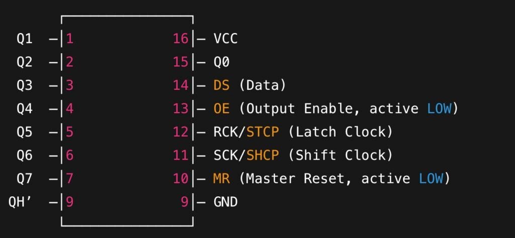
Key Pins
-
DS (Serial Data Input) – Data from the microcontroller.
-
SHCP (Shift Clock) – Moves data into the shift register on rising edge.
-
STCP (Latch Clock) – Transfers data from shift register to outputs.
-
OE (Output Enable) – Enables/disables outputs (active LOW).
-
MR (Reset) – Clears all registers (active LOW).
-
Q0–Q7 – Parallel outputs.
-
QH’ – Serial output, used for daisy chaining multiple chips.
How the 74HC595 IC Works
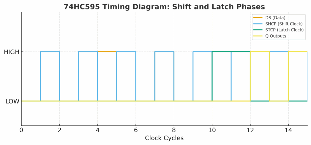
The 74HC595 shift register operates in two simple but powerful phases that make it ideal for expanding microcontroller outputs. In the shift phase, the SHCP (Shift Clock) pin advances the internal register by one bit on every rising edge of the clock. Each pulse pushes the incoming data from the DS (Data) pin deeper into the 8-bit register, much like beads sliding along a wire. Once all eight bits are clocked in, the chip has the complete pattern stored internally.
The next step is the latch phase, controlled by the STCP (Latch Clock) pin. A single pulse on this line transfers the contents of the shift register into the storage register, which directly drives the output pins Q0–Q7. This clever separation between shifting and latching ensures that outputs remain steady and flicker-free while new data is being loaded. Only when you toggle the latch do all outputs update simultaneously, resulting in clean, synchronized transitions across your LEDs or display segments.
The chip works in two phases:
-
Shift phase (SHCP): Each clock pulse shifts one data bit into the register.
-
Latch phase (STCP): Data is copied from the shift register into the storage register, updating the outputs.
This separation ensures outputs remain stable while new data is shifted in.
Daisy Chaining: Expanding Outputs
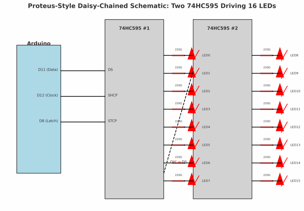
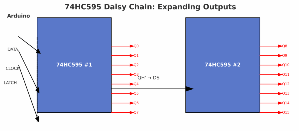
One of the most powerful features of the 74HC595 is its ability to daisy-chain. The logic IC includes a serial output pin, QH′ (pin 9), which carries the last bit shifted through the register. By wiring QH′ from one chip into the DS input of the next, multiple 74HC595 devices can be chained together. Each additional chip adds another 8 outputs, all controlled by the same three microcontroller pins—DATA, CLOCK, and LATCH.
For example, chaining two chips gives you 16 outputs, three chips provide 24 outputs, and so on, effectively allowing “infinite” expansion. A single latch pulse still updates every chip at once, so your entire LED matrix, row of 7-segment displays, or bank of relays switches in perfect unison.
This combination of simplicity, scalability, and stable output makes the 74HC595 one of the most popular ICs for expanding Arduino and microcontroller projects.
74HC595 Datasheet Highlights
Before using the 74HC595 shift register in your design, it’s worth looking at the most important details from the 74HC595 Datasheet. These parameters determine how the chip behaves electrically and help ensure you don’t exceed its safe operating limits.
The 74HC595 Datasheet specifies a supply voltage range of 2.0V to 6.0V, which means the chip works seamlessly with both 3.3V and 5V microcontrollers. This flexibility makes it suitable for everything from Arduino boards to modern low-voltage MCUs. At 5V, the device can handle a maximum clock frequency of around 55 MHz, more than fast enough for LED driving, display refreshing, or general-purpose output control.
In terms of current, the 74HC595 Datasheet notes a typical output drive of ±6mA per pin. While the absolute maximum rating is 20mA per output, it’s not recommended to run the chip at that level continuously, as it can stress the IC and reduce its lifespan. Instead, the 74HC595 should be used for low-current tasks, such as driving LEDs through current-limiting resistors. For higher loads like LED strips, motors, or relays, the 74HC595 Datasheet recommends pairing the outputs with external drivers such as transistors or MOSFETs.
In short, the 74HC595 Datasheet shows that this IC excels in speed, efficiency, and logic-level compatibility, but it isn’t meant to directly handle power-hungry devices. Keeping these limits in mind ensures reliable, long-term performance in your circuit designs.

-
Supply Voltage (VCC): 2.0V – 6.0V
-
Max Frequency: ~55 MHz (at 5V)
-
Typical Output Current: ±6mA per pin
-
Absolute Max Output Current: 20mA (not recommended for continuous use)
👉 Important: The 74HC595 cannot directly drive high-current loads (like LED strips or motors). Use transistors or MOSFETs when more current is required.
How to Use the 74HC595
Wiring the 74HC595 with Arduino
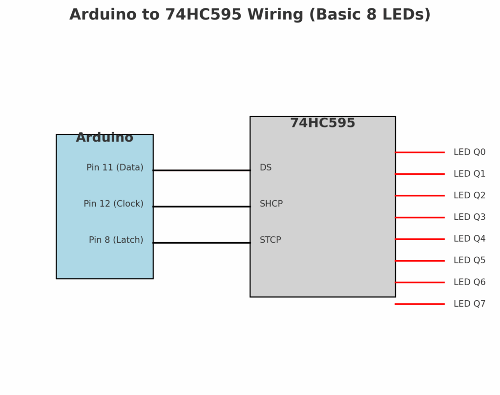
Here’s a typical wiring to control 8 LEDs. The 74HC595 needs only three control lines from the Arduino—DS (Data), SHCP (Shift Clock), and STCP (Latch Clock)—to drive eight outputs. In a typical setup:
-
74HC595 Pin 14 (DS) → Arduino Pin 11 (data line)
-
Pin 11 (SHCP) → Arduino Pin 12 (clock line)
-
Pin 12 (STCP) → Arduino Pin 8 (latch line)
-
OE (Output Enable) → GND (always enabled)
-
MR (Master Reset) → VCC (disabled so the register isn’t cleared)
-
Q0–Q7 → LEDs through 220Ω resistors to limit current
This arrangement ensures that serial data is clocked in bit by bit on the data line. Once all 8 bits are shifted in, a pulse on the latch pin updates all outputs at once, preventing flicker or partial updates.
Arduino Example Code (ShiftOut)
// 74HC595 Arduino Example
int dataPin = 11; // DS
int clockPin = 12; // SHCP
int latchPin = 8; // STCPvoid setup() {
pinMode(dataPin, OUTPUT);
pinMode(clockPin, OUTPUT);
pinMode(latchPin, OUTPUT);
}void loop() {
for (int i = 0; i < 256; i++) {
digitalWrite(latchPin, LOW); // begin update
shiftOut(dataPin, clockPin, MSBFIRST, i); // send data
digitalWrite(latchPin, HIGH); // latch to outputs
delay(200);
}
}
👉 This code cycles through all 256 patterns (2^8 combinations), turning LEDs on and off in sequence. It’s a simple way to test your wiring and understand how bits translate to outputs.
Chaining Two 74HC595 Chips
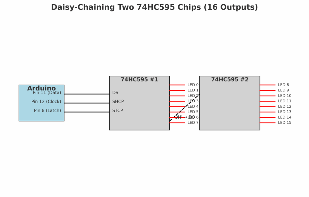
One of the biggest advantages of the 74HC595 is that it supports daisy chaining. By connecting the QH′ pin of the first IC to the DS pin of the second, you can shift data through the first register and into the next. Both chips share the same clock and latch signals, so they update in sync.
// Two chained 74HC595 controlling 16 LEDs
void loop() {
for (int i = 0; i < 65536; i++) {
digitalWrite(latchPin, LOW);
shiftOut(dataPin, clockPin, MSBFIRST, (i >> 8)); // high byte
shiftOut(dataPin, clockPin, MSBFIRST, i & 0xFF); // low byte
digitalWrite(latchPin, HIGH);
delay(50);
}
}
👉 With two chips, you now have 16 outputs from just 3 Arduino pins. This code counts through 65,536 states (2^16), showing how data flows seamlessly through chained registers.
Practical Notes
-
Speed: For most LED applications,
shiftOut()is fine. But if you chain many chips, switch to hardware SPI for faster updates. -
Current handling: Each output can source/sink about 6mA safely. For bright LEDs, use transistors or MOSFETs.
-
Global dimming: Connect OE to a PWM pin instead of GND to adjust brightness of all LEDs together.
-
Reset: Tie MR high in most cases, but you can drive it LOW to clear all outputs instantly.
With these techniques, the 74HC595 becomes a powerful building block: whether you’re controlling an LED bar graph, driving multiple 7-segment displays, or managing relays, this IC expands your Arduino’s capability far beyond its onboard GPIOs.
Common Applications of the 74HC595 IC
The 74HC595 shift register is one of the most versatile ICs in electronics, thanks to its ability to expand the number of outputs from a microcontroller while using only a few pins. This makes it a go-to solution in many practical projects and commercial products.
One of the most popular uses is driving LED matrices and bar graphs. Instead of dedicating a large number of I/O pins to individual LEDs, the 74HC595 lets you send serial data and then display it as parallel outputs, lighting up entire rows or columns efficiently. This approach is widely used in scrolling text displays, dot-matrix boards, and status indicators.
Another common application is multiplexed 7-segment displays. By chaining multiple 74HC595 chips together, you can control multi-digit numerical displays with minimal wiring, which is especially useful in digital clocks, counters, and electronic measuring instruments. The latch mechanism ensures all digits update simultaneously, preventing flicker and ensuring readability.
The IC also finds use in LCD interface expansion, where it acts as a bridge between a microcontroller and a display. By sending commands and data serially to the 74HC595, you can easily control the multiple parallel pins required by an LCD without exhausting your MCU’s GPIO resources.
In more demanding environments, the 74HC595 is frequently integrated into industrial control systems and automation setups. It can be used to buffer and distribute control signals across large systems, often paired with external driver circuits for higher current loads. This ensures reliable switching of indicators, alarms, and basic electromechanical devices.
Finally, in robotics and embedded control systems, the 74HC595 plays an important role in controlling relays, actuators, or motor drivers. Since each pin can source or sink only a limited current, the chip is often combined with transistors or MOSFETs to drive higher power loads, enabling precise and scalable robotic movement or automation control.
In short, the 74HC595 IC is a building block that bridges the gap between compact microcontrollers and complex real-world hardware, making it indispensable in both hobbyist and professional electronics design.
-
Driving LED matrices and bar graphs
-
Multiplexed 7-segment displays
-
LCD interface expansion
-
Industrial control systems and automation
-
Robotics (controlling relays or actuators with extra drivers)
FAQ About TI 74HC595 IC
Q1. Can the 74HC595 drive 20mA on each pin?
Not safely. The 74HC595 datasheet specifies a typical current drive of about ±6mA per pin, with 20mA listed as an absolute maximum. Running each output at 20mA continuously risks overheating the IC and drastically reducing its lifespan. If you need to drive higher-current devices such as LED strips, relays, or motors, it’s best to connect the outputs of the 74HC595 to transistor or MOSFET driver stages. This way, the shift register only handles logic-level signals, while the external drivers handle the heavier current safely.
Q2. What’s the difference between 74HC595D and SN74HC595N?
Functionally, both are identical 74HC595 shift registers, but they come in different packages. The 74HC595D uses an SOIC package designed for surface-mount devices (SMD), making it compact and suitable for modern PCB manufacturing. The SN74HC595N, on the other hand, comes in a DIP-16 through-hole package, which is breadboard- and prototyping-friendly. If you’re just experimenting or building with Arduino, the SN74HC595N is easier to use. If you’re designing a compact production PCB, the 74HC595D is the preferred choice.
Q3. How many chips can I chain together?
In theory, you can daisy-chain as many 74HC595 chips as you want, since each chip passes data through its QH′ serial output into the next one’s DS input. In practice, however, there are limitations. Signal integrity and timing start to degrade after chaining many chips, especially at higher clock speeds. Designers often chain 8–16 chips without issues, which gives you up to 128 outputs from just 3 MCU pins. If you need even more, you may need buffering or slower clock speeds to maintain reliability.
Q4. Can I simulate 74HC595 in Proteus?
Yes. Proteus provides models of the 74HC595 that you can place in your schematic. This allows you to test the wiring, run Arduino sketches (using the Virtual Terminal or Arduino library in Proteus), and even visualize LEDs connected to Q0–Q7. Simulation is a great way to debug your design before moving to hardware. Just remember that simulation won’t perfectly model real-world effects such as noise, propagation delays, or current limits, so you should still test with physical components for final validation.
Conclusion
The 74HC595 shift register remains one of the simplest, most cost-effective ways to multiply a microcontroller’s outputs. With just three control lines you gain eight latched channels per chip, and by daisy-chaining devices through QH′→DS you can scale cleanly in blocks of eight without redesigning your I/O. For hobby builds and production PCBs alike, the part is inexpensive, widely stocked, and predictable—exactly what you want when you’re driving LEDs, 7-segment displays, indicator banks, or simple relay interfaces.
What makes the 74HC595 especially practical is its separation of shifting and latching: you can load new data in the background and update every output in one crisp pulse, avoiding flicker and timing glitches. Tie OE low for always-on outputs, or place it on a PWM pin for global brightness control. Keep a 0.1 µF decoupling capacitor at VCC, use current-limiting resistors for each LED, and pair the outputs with transistors/MOSFETs when you need more current than the chip is designed to supply. If you outgrow shiftOut(), switch to hardware SPI for higher refresh rates and longer chains with cleaner timing.
If you’re new to microcontrollers, mastering the 74HC595 is a high-leverage skill: it teaches clocked serial data, latching, signal integrity, and modular design. Start with a single chip to light a row of LEDs, then chain two or three to drive a display or status panel, and finally migrate to SPI as your projects scale. Do that, and you’ll find the 74HC595 isn’t just a handy part—it’s a reliable building block for flexible, scalable control systems.
