ESD24VS2UE6327 Infineon ESD24VS2UE6327 TVS Diode – 24 V, SOT-23, Low-Capacitance Protection for CAN/LIN & 12/24 V Lines
- Automotive-grade protection: Survives ±30 kV IEC 61000-4-2 ESD and 5 A (8/20 µs) surge for CAN/LIN and 12/24 V rails.
- Signal-friendly capacitance: ~24 pF typ. line-to-line to preserve bus edges and bandwidth.
- Flexible SOT-23 pinout: Two-line unidirectional or single-line bidirectional (pins 1–2) by leaving pin 3 floating.
ESD24VS2UE6327 Transient Voltage Suppressor TVS Diodes for CAN/LIN & 12/24 V Lines Overview
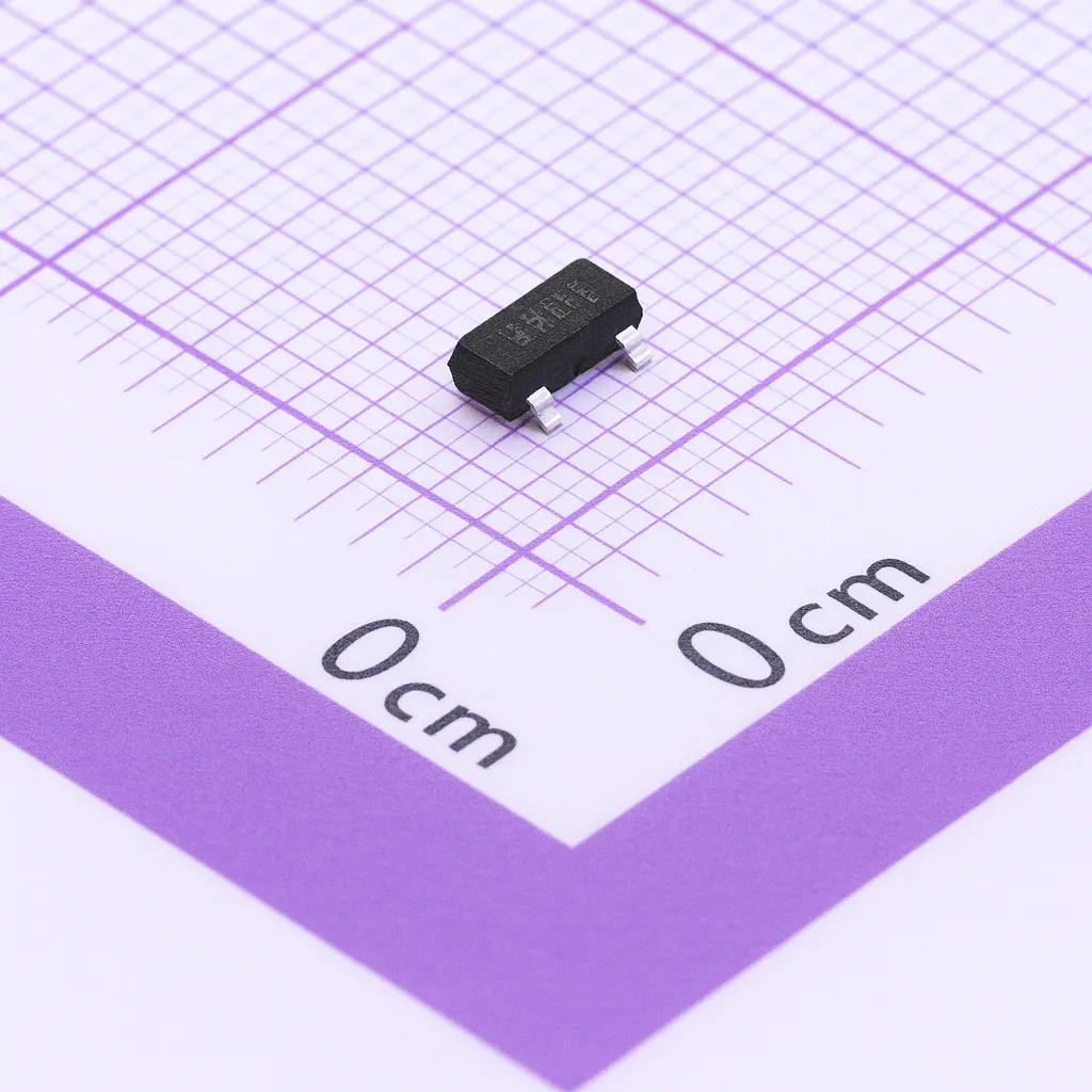
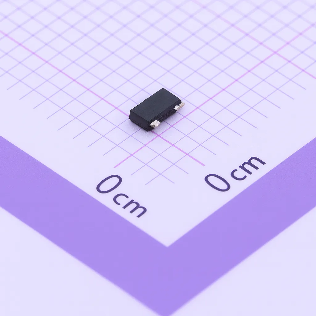
The Infineon ESD24VS2UE6327 (family: ESD24VS2U) is a silicon transient voltage suppressor (TVS) diode designed to harden 12 V/24 V power rails and serial data interfaces such as CAN and LIN against electrostatic discharge (ESD), electrical fast transients (EFT), surge events, and automotive ISO 7637-2 pulses. Packaged in a compact SOT-23 footprint, it protects two lines in unidirectional mode (or a single bidirectional line between pins 1 and 2 when pin 3 is left unconnected), making it a versatile choice for automotive body electronics, industrial control networks, and robust 24 V systems.
Engineered for harsh environments, the device is qualified to withstand IEC 61000-4-2 ESD of ±30 kV (air/contact), IEC 61000-4-4 EFT of 80 A (5/50 ns), and IEC 61000-4-5 surge of 5 A (8/20 µs)—levels sufficient for most vehicle and factory installations. It also addresses ISO 7637-2 pulses used to characterize disturbances on automotive supply lines (Pulse 1, Pulse 2, Pulse 3a/3b).
Despite this resilience, the part remains signal-friendly: the typical line-to-line capacitance is just 24 pF, with a low clamping voltage (< 41 V at 5 A) and ultra-low leakage current (typ. < 1 nA) that helps keep standby power minimal and signal integrity high. Its maximum working voltage (VRWM) is 24 V, matching common 12/24 V rails and truck/bus systems.
Two application topologies are supported and illustrated in the datasheet: (1) unidirectional protection to ground for 12/24 V rails—recommended with pin 3 tied directly to a ground plane and the device placed close to the threat entry point; and (2) bidirectional, line-to-line protection for single-wire CAN and LIN buses when pin 3 is not connected. Layout guidance emphasizes minimizing loop area and inductance between the connector and the TVS.
Beyond the headline immunity levels, the datasheet provides measured clamped waveforms to ISO 7637-2 pulses: for Pulse 1 (-50 V open-circuit), the line is clamped to about -34.8 V with the diode; for Pulse 2a (+125 V), clamping is about 36.0 V; and for Pulse 3 (+800 V), clamping is about 40.0 V—useful real-world references when validating designs.
Specifications — Infineon ESD24VS2UE6327 (SOT-23)
Tip: Values below summarize the datasheet highlights. See the electrical characteristics table (page 2), application diagrams (page 5), ISO 7637-2 clamp results (pages 6–8), and mechanical data (page 9) for full context.
| Parameter | Value |
|---|---|
| Device type | Silicon TVS diode for ESD/transient protection (2 lines, uni-directional; optional 1-line bidirectional between pins 1–2 if pin 3 is NC) |
| Package | SOT-23; marking “EUs” (type code as per page 1); standard SOT-23 outline and footprint on page 9 |
| Protected interfaces | 12/24 V DC supply rails; CAN/LIN/single-wire CAN; industrial control networks (page 1) |
| Max working voltage (VRWM) | 24 V (line to ground) |
| Breakdown voltage (V(BR) @ I(BR)=1 mA) | 26 V min, 32 V max (page 2) |
| Reverse leakage (IR @ 24 V) | typ. < 1 nA; max 10 nA (page 2) |
| Line capacitance (CT) | 24 pF typ (pins 1–2, pin 3 n.c.); 28 pF max (same condition). 48 pF typ from line to pin 3 (page 2 & page 4). |
| Clamping voltage (VCL @ 8/20 µs) | 30 V typ @ 1 A; 36 V max @ 1 A. 34 V typ @ 5 A; 41 V max @ 5 A (page 2; clamping graphs page 3). |
| Peak pulse current (IPP) | 5 A (8/20 µs), per IEC 61000-4-5 (page 2) |
| Peak pulse power (PPK) | 230 W (8/20 µs) (page 2) |
| IEC 61000-4-2 ESD immunity | ±30 kV (air/contact), 10 positive/negative pulses (page 1, page 2 note) |
| IEC 61000-4-4 EFT immunity | 80 A (5/50 ns) (page 1) |
| ISO 7637-2 pulses | Pulse 1 (max −50 V), Pulse 2 (max +125 V), Pulse 3a/b (up to 800 V); measured clamping examples: −50 V to −34.8 V, +125 V to 36 V, 800 V to 40 V (pages 6–8). |
| Operating temperature (TOP) | −55 °C to +150 °C (page 2) |
| Storage temperature (TSTG) | −65 °C to +150 °C (page 2) |
| Power derating | See PPK vs TA curve (page 3); consider current de-rating at high TA. |
| Reverse current vs. VR, TA | Curves provided (page 3) to estimate leakage across temperature. |
| Capacitance vs. VR | CT vs VR plotted at 1 MHz (page 4) to aid signal integrity calculations. |
| Application diagrams | 12/24 V rail protection (uni-directional); single-wire CAN/LIN protection (bidirectional line) on page 5. |
| Reel quantities | ~3,000 pcs/Ø180 mm reel; ~10,000 pcs/Ø330 mm reel (page 9). |
| Compliance | Pb-free, RoHS-compliant package (page 1). |
Applications — Where the ESD24VS2UE6327 Excels
Automotive networks (12/24 V):
The ESD24VS2UE6327 is tailored for CAN, LIN, and single-wire CAN nodes exposed to transients from cable insertion, load dumps (via coupling networks), and ESD strikes at connectors. With ±30 kV ESD robustness and ISO 7637-2 pulse handling demonstrated in the datasheet waveforms, it is a solid choice for body control modules, lighting controllers, infotainment head units, and sensor gateways in both passenger and commercial vehicles. Use the bidirectional connection (pins 1–2, pin 3 NC) for single-wire buses per the page 5 diagram; the low typ. capacitance helps preserve bus edges and EMC headroom.
Industrial control and PLC I/O:
24 V DC rails and field-bus lines in factories are routinely hit by EFT bursts and nearby switching surge events. The device’s 80 A EFT rating (5/50 ns) and 5 A surge capability (8/20 µs) help clamp those disturbances to safe levels. The very low leakage current keeps quiescent losses negligible in always-on controllers, remote I/O terminals, and distributed power nodes — a crucial advantage in designs striving for minimal standby energy.
12 V/24 V power input protection for embedded systems:
For gateway boards, telematics modules, or industrial PCs, place the TVS close to the input connector as Infineon recommends (page 5) to minimize loop inductance and achieve the specified clamp performance. Tie pin 3 directly to a solid ground plane and keep the protected trace short into your DC/DC converter or LDO. The clamping behavior shown on pages 6–8 provides empirical guidance for selecting downstream component voltage ratings and setting protection thresholds.
Communication and sensor lines:
Beyond CAN/LIN, the part also suits other moderate-speed interfaces that need 24 V headroom. Its capacitance-versus-bias curve (page 4) supports eye-diagram budgeting and filter design; you can estimate added loading under operating bias to ensure signal integrity stays within spec.
Design Notes & Integration Tips
-
Choose the right topology:
-
Uni-directional (two lines): Protect two separate 24 V rails or two signal lines referenced to ground, using pins 1→3 and 2→3.
-
Bidirectional (single line): For single-wire buses, connect between pins 1 and 2 with pin 3 left unconnected (page 1 note and page 5 diagram).
-
-
Layout is protection:
Place the TVS as close as possible to the entry point of the threat (e.g., I/O or power connector). Keep the return to the ground plane short and wide; avoid vias in the protected path if possible, and route the downstream trace from the TVS to the transceiver or regulator with minimum loop area (page 5 guidance). -
Understand clamping in your system context:
The oscilloscope plots (pages 6–8) illustrate clamp levels under ISO 7637-2 pulses with defined source impedance. Real systems can differ, so use the listed VCL values (page 2 and clamping curves on page 3) alongside your harness impedance and cable lengths to simulate peak component stresses. Consider adding series resistors or common-mode chokes where needed to further shape the surge current. -
Thermal and surge budgeting:
Respect the 230 W peak pulse power rating at 8/20 µs and verify the derating curve vs ambient temperature (page 3). Elevated ambient or restricted airflow will reduce allowable pulse energy; the graph helps you set conservative design margins for worst-case scenarios. -
Signal integrity awareness:
Leverage the capacitance-versus-voltage plot at 1 MHz (page 4) to quantify added load at the line’s DC bias and expected ripple. For high-speed CAN (up to 1 Mbps and beyond), the 24 pF typ. between pins 1–2 (pin 3 NC) enables robust protection with minimal rise-time degradation. -
Manufacturing & logistics:
SOT-23 offers broad assembly compatibility. Refer to page 9 for the exact land pattern, pin-1 identification, and tape-and-reel dimensions; standard reels are ~3,000 pcs (Ø180 mm) and ~10,000 pcs (Ø330 mm), streamlining high-volume SMT processes.
Why Choose the ESD24VS2UE6327?
-
Automotive-proven immunity: Its alignment with ISO 7637-2 pulses (and published clamp screenshots) gives confidence for in-vehicle DC networks — including 24 V commercial fleets.
-
Low-leakage protection that’s “always on”: With typ. sub-nanoamp reverse current at VRWM, there’s negligible standby penalty, critical for battery-powered nodes and modules that sleep frequently.
-
Small, flexible, and simple: One SOT-23 device can protect two grounded lines or one floating line bidirectionally, reducing BOM count and conserving PCB space, while the provided footprint and packing details simplify sourcing and assembly.
Infineon ESD24VS2UE6327 TVS Diode Detailed Description
The ESD24VS2UE6327 integrates fast-acting junctions optimized for transient suppression on 24 V systems. Under normal operation, the device presents high impedance, leaking typically under one nanoamp at 24 V (page 2) to avoid loading the bus or wasting battery power. When a surge or ESD strike occurs, the junctions avalanche quickly and clamp the line to a safe voltage. The clamping performance is specified both numerically (page 2) and graphically (page 3), letting engineers correlate data sheet numbers to wave-shape expectations.
Clamping performance in context:
At 1 A (8/20 µs), clamping is typically around 30 V (≤ 36 V max), and at 5 A it remains around 34 V typ (≤ 41 V max). These levels are well-matched to 24 V electronics using 30–40 V-rated components downstream (e.g., 36 V-rated DC/DC converters or 40 V-rated transceivers), ensuring that a properly routed TVS drastically reduces the probability of electrical overstress. The ISO 7637-2 examples (pages 6–8) bolster this: a −50 V pulse is clamped to roughly −34.8 V; a +125 V pulse is constrained to ~36 V; and a fast +/−800 V pulse (50 Ω source) is limited to about 40 V at the node.
Capacitance and signaling:
Signal integrity is often the trade-off in protection. Here, the 24 pF typ. between pins 1–2 (with pin 3 open) keeps added capacitive loading modest. The CT vs VR curve (page 4) shows how capacitance changes with bias, an important consideration on biased buses or rails with ripple. For uni-directional use (line-to-ground), capacitance is slightly higher line-to-pin 3 (~48–52 pF typ./max) — still low enough for power rails and many control lines.
Thermal margins and reliability:
With a 230 W peak pulse power rating (8/20 µs) and an operating range up to +150 °C (page 2), the device tolerates automotive and industrial ambients. Use the derating curve (page 3) to adapt your transient budget at higher TA; consider pulse repetition and spacing if your worst-case scenario involves multiple hits.
Mechanical and production details:
SOT-23 pinout and recommended land pattern on page 9 make it straightforward to integrate into dense boards; the marking layout helps with AOI and incoming inspection, and the reel formats (≈3k/≈10k) fit modern pick-and-place lines. Being Pb-free/RoHS-compliant eases environmental and regulatory requirements across global markets.
Typical Use Cases
-
CAN/LIN transceiver protection at body control modules, door nodes, HVAC controllers, instrument clusters, and telematics units. Use bidirectional pins 1–2 (pin 3 NC) for single-wire buses per the page 5 schematic.
-
24 V PLC and machine controllers, shielding the input power and I/O lines from EFT and inductive kickback; mount near the terminal block as recommended to minimize loop inductance (page 5).
-
Embedded power entry protection for industrial PCs, gateways, and communication bridges that see frequent hot-plug events or cable ESD.
Three Notable Advantages
-
Automotive-grade transient immunity (IEC 61000-4-2/-4/-5 + ISO 7637-2 waveforms shown) that shortens qualification cycles.
-
Low leakage, low capacitance design, ideal for battery-powered modules and communication lines that need clean edges.
-
Flexible 2-in-1 topology (two uni-directional lines or one bidirectional line) to reduce BOM count and save space.
Ordering & Packaging
-
Part: ESD24VS2UE6327 (SOT-23).
-
Marking: “EUs” (type code; see page 1 for table; page 9 shows example marking layout and pin-1 ID).
-
Reel options: ~3,000 pcs (Ø180 mm) or ~10,000 pcs (Ø330 mm) per page 9 “Standard Packing.”
For full legal disclaimers and usage in safety-critical systems, refer to the notices on the final page of the datasheet.
Specification: Infineon ESD24VS2UE6327 TVS Diode – 24 V, SOT-23, Low-Capacitance Protection for CAN/LIN & 12/24 V Lines
|
User Reviews
Only logged in customers who have purchased this product may leave a review.


There are no reviews yet.