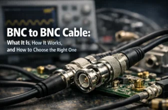
The main difference between NPN and PNP transistors is the direction of current flow and the polarity needed to turn them on. In practical applications, NPN devices are usually used for low-side switching and sinking outputs, while PNP devices are used for high-side switching and sourcing outputs. This matters when reading transistor symbols, wiring proximity sensors, and matching sensor outputs to PLC input types.
Transistors are among the most important components in electronics, but many engineers, buyers, and maintenance teams still get confused when comparing NPN vs PNP devices. The difference is not limited to the symbol on a schematic. It also affects how the transistor turns on, how current flows, and how the device should be connected in a real circuit.
In simple terms, NPN transistors are typically used for low-side switching and sinking outputs, while PNP transistors are used for high-side switching and sourcing outputs. This distinction becomes especially important when choosing a proximity sensor, reading a wiring diagram, or connecting a sensor to a PLC input.
NPN vs PNP at a Glance
| Feature | NPN | PNP |
|---|---|---|
| Symbol arrow | Points out of the emitter | Points into the emitter |
| Turn-on condition | Base is more positive than emitter | Base is more negative than emitter |
| Conventional current path | Collector to emitter | Emitter to collector |
| Typical switching role | Low-side switching | High-side switching |
| Sensor output type | Sinking | Sourcing |
| Active output behavior | Pulls output to 0V | Pulls output to positive voltage |
| Best use case | When the circuit expects pull-down behavior | When the circuit expects positive output |
What Is an NPN Transistor?
An NPN transistor is a type of bipolar junction transistor made of three semiconductor layers arranged as Negative–Positive–Negative. It has three terminals: collector, base, and emitter. NPN transistors are widely used in amplification and switching circuits because they are easy to drive from many logic systems and are commonly used as low-side switches.
NPN transistor symbol
The easiest way to identify an NPN transistor is by looking at the arrow on the emitter. In an NPN symbol, the arrow points outward. This is one of the fastest ways to distinguish it from a PNP transistor on a schematic.
How an NPN transistor works
An NPN transistor turns on when the base voltage is higher than the emitter voltage. A small current entering the base allows a larger current to flow from the collector to the emitter. That is why NPN transistors are often used in switching circuits, amplifier stages, relay drivers, and sensor outputs.
What Is a PNP Transistor?
A PNP transistor is another type of bipolar junction transistor, made of Positive–Negative–Positive semiconductor layers. Like the NPN transistor, it has collector, base, and emitter terminals. The main difference is the polarity needed to turn it on and the direction of current flow in conventional circuit analysis.
PNP transistor symbol
In a PNP transistor symbol, the arrow points inward, toward the transistor body. This inward arrow is the most recognizable visual difference between NPN vs PNP symbols.
How a PNP transistor works
A PNP transistor turns on when the base voltage is lower than the emitter voltage. In this condition, current can flow from the emitter to the collector. PNP transistors are commonly used for high-side switching, positive rail control, and sourcing outputs.
NPN = Not Pointing iN
PNP = Pointing iN
NPN vs PNP Symbol: How to Tell the Difference
When comparing NPN vs PNP transistors, the symbol is often the fastest way to identify which one you are working with. The emitter arrow tells you what type of transistor you are looking at:
NPN Symbol
Arrow points out of the emitter.
Commonly associated with low-side switching and sinking behavior.
PNP Symbol
Arrow points in toward the emitter.
Commonly associated with high-side switching and sourcing behavior.
Knowing how to read the symbol helps you identify the transistor quickly, understand how the circuit is supposed to work, and avoid wiring mistakes when replacing parts or troubleshooting field failures.
NPN vs PNP Working Principle Explained
Current flow in an NPN transistor
In conventional current analysis, current flows from the collector to the emitter when the transistor is on. This makes NPN devices a natural choice for low-side switching, where the transistor sits between the load and ground.
Current flow in a PNP transistor
In a PNP transistor, conventional current flows from the emitter to the collector when the transistor is on. This makes PNP devices more suitable for high-side switching, where the transistor controls the positive supply side.
Key practical difference
If you want to simplify the comparison:
- NPN transistors pull the load toward ground
- PNP transistors pull the load toward the positive supply
Neither NPN nor PNP is universally “better.” The correct choice depends on the circuit design, controller input logic, supply arrangement, and whether the system expects sinking or sourcing behavior.
NPN vs PNP Sensors: What’s the Difference?
The phrase NPN vs PNP is especially common in automation because many users are actually comparing sensor outputs, not just discrete transistors.
What is an NPN sensor?
An NPN sensor provides a sinking output. When the sensor is activated, its output is connected internally to 0V (ground). Instead of supplying positive voltage to the load, it creates a path to ground so current can flow.
What is a PNP sensor?
A PNP sensor provides a sourcing output. When the sensor is activated, its output is connected internally to the positive supply voltage. In other words, it sends a positive signal to the input when detection occurs.
NPN vs PNP proximity sensor
A proximity sensor may use the same sensing method whether it is NPN or PNP. The difference is usually not in how it detects the object, but in how the output behaves electrically. That is why two sensors with similar size and voltage ratings may still not be interchangeable.
NPN vs PNP Wiring Diagram and Connection Logic
How to wire an NPN sensor
In an NPN sensor circuit, the output switches to ground when active. The load or PLC input is typically connected toward the positive supply, and the sensor completes the path to 0V. This is why NPN outputs are called sinking outputs.
How to wire a PNP sensor
In a PNP sensor circuit, the output switches to positive voltage when active. The load or PLC input is typically referenced toward 0V, and the sensor supplies current to the input. This is why PNP outputs are called sourcing outputs.
Typical 3-wire sensor logic
Many industrial sensors use three wires:
- Brown = positive supply
- Blue = 0V
- Black = output signal
The key difference between NPN and PNP is what the black output wire does when the sensor is activated.
Common wiring mistakes to avoid
- Connecting an NPN sensor to an input that expects PNP output
- Ignoring the PLC input common terminal arrangement
- Assuming matching wire colors mean matching output type
- Replacing a failed sensor without checking output logic
- Misunderstanding sinking vs sourcing terminology
NPN vs PNP for PLC Inputs and Industrial Automation
One of the most common real-world questions is whether NPN or PNP is better for PLC systems. The practical answer is simple: use the one that matches the PLC input design.
How to check PLC compatibility
- Check the PLC input type
- Check the common terminal arrangement
- Read the wiring diagram in the PLC manual
- Confirm whether the input expects sourcing or sinking behavior
If the PLC input is designed to receive a positive-going signal, a PNP sensor is usually the correct choice. If the PLC input is designed to detect a path to ground, an NPN sensor is typically required.
How to Choose Between NPN and PNP Transistors or Sensors
1. Check the controller
Confirm whether the input expects sourcing, sinking, pull-up, or pull-down logic.
2. Match existing wiring
If you are replacing a sensor, match the original output type unless the control logic is being redesigned.
3. Check load connection
Decide whether the switching element should connect the load to ground or to positive supply.
Quick decision rule:
- Choose PNP when the input expects a positive signal
- Choose NPN when the input expects the signal to be pulled to ground
Common NPN & PNP Transistor Manufacturers and Popular NPN/PNP Models
Beyond symbol and wiring differences, many readers also want to know which NPN and PNP transistor families are most common in real-world design, sourcing, and replacement scenarios.
When comparing NPN vs PNP transistors, it also helps to know which manufacturers and model families are commonly seen in practical projects. In real applications, engineers often work with general-purpose BJTs from brands such as onsemi, STMicroelectronics, Nexperia, and Microchip, while industrial automation buyers will often come across brands such as Omron Automation in the proximity sensor category.
Common NPN transistor examples
One of the most widely recognized small-signal NPN transistor families is the 2N3904. Readers can also explore the onsemi 2N3904BU, a general-purpose NPN BJT used for switching and amplification. For broader sourcing, the BJTs category also includes NPN examples such as Microchip JANTXV2N3700UB and Microchip JANTX2N6383.
Common PNP transistor examples
On the PNP side, the best-known companion part to the 2N3904 is the 2N3906, which is commonly used in low-power amplification and high-side switching applications. The 2N3904 transistor guide also references the 2N3906 when explaining NPN versus PNP behavior. In addition, the BJTs category currently includes PNP examples such as Microchip JANTX2N6987 and Microchip JANTX2N3635UB.
Common sensor and automation brands
For readers focused on automation rather than discrete transistor design, brand familiarity is also useful. The Proximity Sensors category is a natural next step for users comparing NPN vs PNP output types in industrial environments, while the Manufacturers index helps readers browse major electronics brands such as onsemi, Nexperia, STMicroelectronics, and Omron Automation before moving from theory into actual component sourcing.
Knowing these common manufacturers and model families makes it easier to compare datasheets, find alternatives, and move from theory into actual sourcing and replacement decisions.
Common NPN vs PNP Mistakes
- Assuming NPN and PNP are directly interchangeable
- Reading the emitter arrow incorrectly
- Ignoring sensor output polarity
- Misunderstanding sinking vs sourcing
- Replacing a sensor without checking PLC input compatibility
How to Test Whether a Sensor Is NPN or PNP
If you are unsure whether a sensor is NPN or PNP, use the following steps:
- Check the datasheet for “NPN output,” “PNP output,” “sinking,” or “sourcing.”
- Check the product label or part number for output type indicators.
- Measure the output wire with a multimeter while the sensor is activated.
- If the output switches toward 0V, it is usually NPN.
- If the output switches toward positive voltage, it is usually PNP.
Frequently Asked Questions About NPN vs PNP
What is the main difference between NPN and PNP?
The main difference is polarity and current flow direction. NPN transistors typically switch the ground side and provide sinking behavior, while PNP transistors switch the positive side and provide sourcing behavior.
Is NPN sinking or sourcing?
NPN is sinking. When active, the output is pulled toward 0V.
Is PNP sinking or sourcing?
PNP is sourcing. When active, the output provides positive voltage.
How do I identify NPN vs PNP from the symbol?
Look at the emitter arrow. NPN points out, while PNP points in.
Can I replace an NPN sensor with a PNP sensor?
Not always. You can only do that if the controller input and wiring arrangement are compatible with the new output type.
Which is better, NPN or PNP?
Neither is always better. The correct choice depends on the circuit design, input logic, and system requirements.
Final Thoughts on NPN vs PNP Transistors
Understanding NPN vs PNP transistors is essential for anyone working with electronics, automation, sensors, or PLC systems. While the symbol difference is easy to remember once you know the arrow rule, the more important distinction is how each device behaves electrically in a real circuit.
In general:
- NPN = sinking, low-side switching, output to 0V
- PNP = sourcing, high-side switching, output to +V
When choosing between them, focus on system compatibility, not guesswork. If you verify the controller input logic, wiring arrangement, and output requirements first, selecting the right transistor or sensor becomes much easier.
Read Next: 2N3904 NPN Transistor Guide
A practical follow-up for readers who want a real NPN transistor example, pinout, specs, and circuit use cases.
Explore More BJTs
Browse bipolar transistors for switching, amplification, and replacement sourcing.
Browse Proximity Sensors
Useful for readers comparing NPN vs PNP proximity sensor output types in industrial automation.