Basics of Capacitor Symbols
Capacitor symbols are the visual shorthand of electronics. Two parallel lines stand for two plates with a dielectric between them; an added arrow means the value can be adjusted (variable or trimmer); extra marks indicate special types like feed-through or vacuum variable. When a capacitor is polarized, the symbol shows direction: in the IEC style the straight plate is positive and the curved plate is negative.
These drawings communicate electrical intent quickly on a schematic, but they don’t tell you the package size, voltage rating, ESR, or safety class—that information lives in the component’s data fields and footprint. Because teams use different drafting traditions (IEC, ANSI/IEEE, JIS), recognizing the small visual cues prevents assembly mistakes and speeds reviews.
In this guide, we’ll show you how to read the most common capacitor symbols at a glance, understand what each one implies in a circuit, and avoid the easy pitfalls around polarity and standards.
What a Capacitor Symbol Says & What It Doesn’t
Before we jump into the gallery, it helps to be crystal clear about what schematic symbols actually encode—and what they deliberately leave out. Symbols are meant to convey electrical intent at a glance, not to carry manufacturing details.
| Says (Electrical Intent) | Doesn’t Say (Manufacturing Specifics — keep in data/footprint) |
|---|---|
| Fixed vs. variable (diagonal arrow = adjustable) | Package / land pattern / height / pad geometry |
| Trimmer (calibration-only adjustable) | ESR / ESL, ripple current, voltage rating, tolerance |
| Polarized devices — IEC style: straight plate = positive, curved plate = negative | Dielectric class (C0G / X7R / PP), temperature rating, lifetime |
| Special forms: feed-through (EMI on DC feeds), differential / split-stator / butterfly (RF tuning), vacuum variable (HV RF, low loss) | Safety/agency class (X/Y), lifecycle (Active/NRND/EOL), MPN |
Why the separation matters:
-
Fewer mistakes: polarity and function are obvious; footprint and ratings live where tools (BOM/DRC/AOI) can check them.
-
Easy variants: swap packages or alternates without redrawing a schematic.
-
Readable schematics: symbols stay simple; the rich facts sit in component fields.
Different Standards for Capacitor Symbols: IEC vs ANSI vs JIS
Different drafting traditions call out polarity in different ways. Use this quick crosswalk to decode mixed drawings and prevent reversed parts on the PCB.
| Standard | Non-polarized | Polarized | Practical note |
|---|---|---|---|
| IEC | Two straight plates | Straight plate = +, curved = – | Common in EU/Asia; teach the curved-is-negative rule. |
| ANSI/IEEE | Two straight plates | Plates with an explicit “+” on positive | Common in U.S. libraries; polarity spelled out with a plus sign. |
| JIS | Two straight plates | Polarity often shown more explicitly | Close to IEC; conventions tend to be stricter/clearer. |
Tip: When teams mix standards, add silkscreen “+ / –” near electrolytics and repeat polarity in the assembly drawing. This tiny redundancy kills ambiguity and catches errors in AOI.
A Complete Guide for Capacitor Symbols
16 Capacitor Symbols Quick-reference Table
Use this quick-reference table to decode sixteen capacitor symbols at a glance. It shows what each symbol communicates—fixed vs. variable, trimmer, and polarity (in IEC style the straight plate is positive and the curved plate is negative)—along with practical notes on where you’ll see each type used.
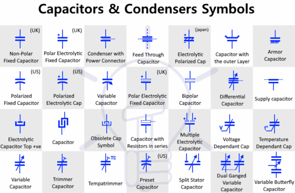
Remember that symbols express electrical intent only; they do not specify package, voltage rating, ESR, ripple, dielectric class, or safety class—keep those in your component fields and footprints. When teams mix IEC/ANSI/JIS libraries, reinforce clarity by adding “+/–” on the PCB silkscreen and repeating polarity in the assembly drawing to eliminate ambiguity.
| Capacitor Symbol | Symbol Name | Polarity | Typical Uses / Notes |
|---|---|---|---|
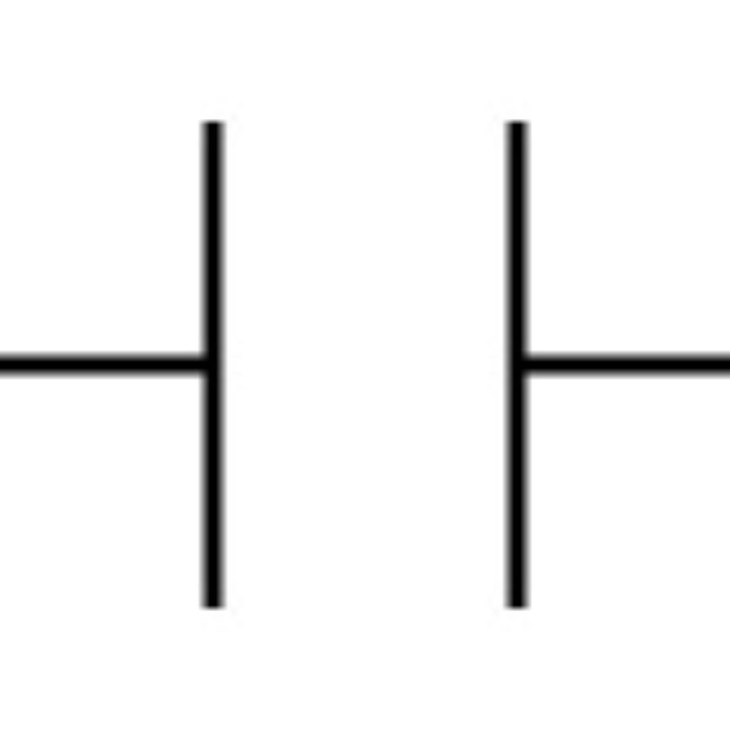 |
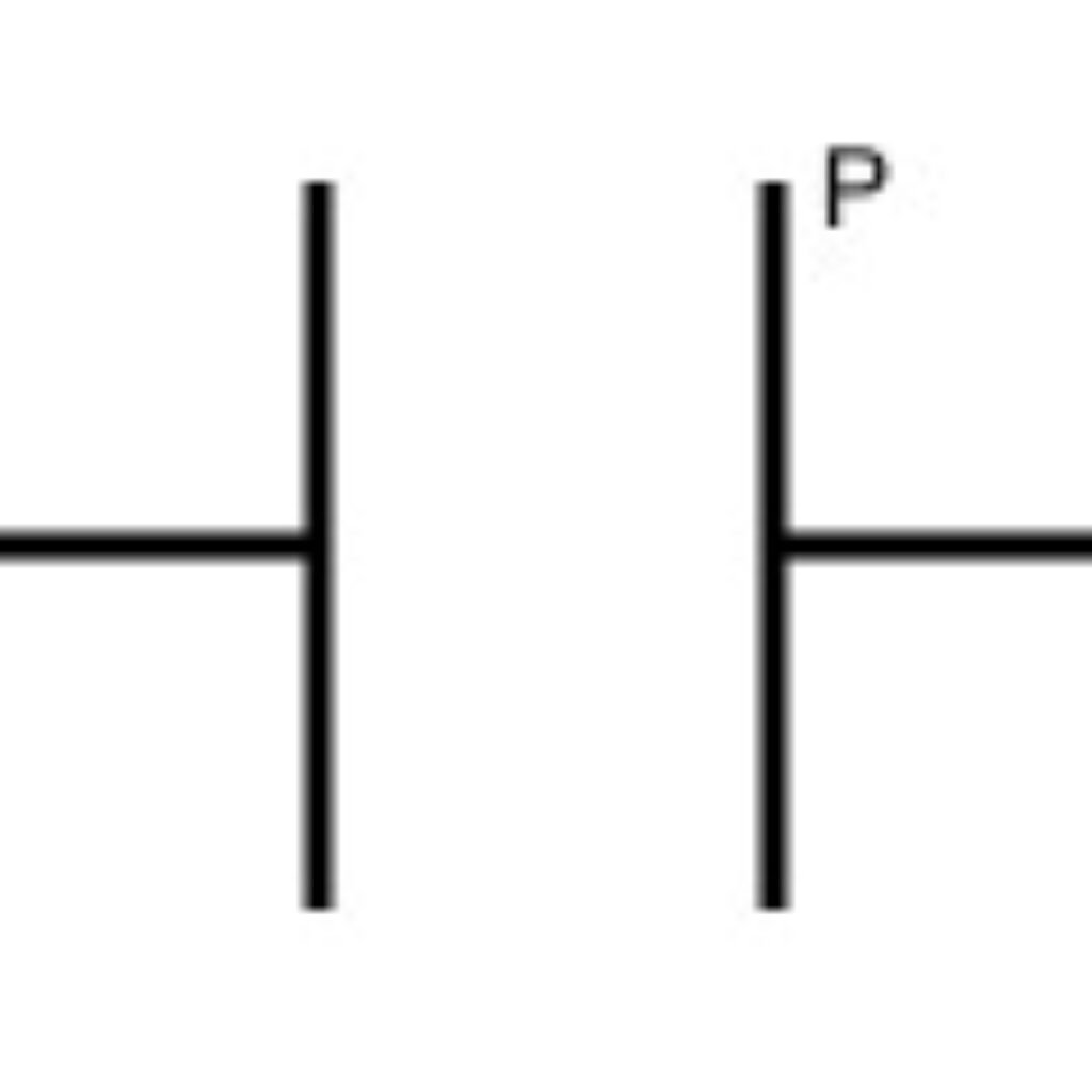
Generic Capacitor (Non-polarized) | No | Two parallel plates; used for ceramics, film, mica. General coupling, bypass, filtering. |
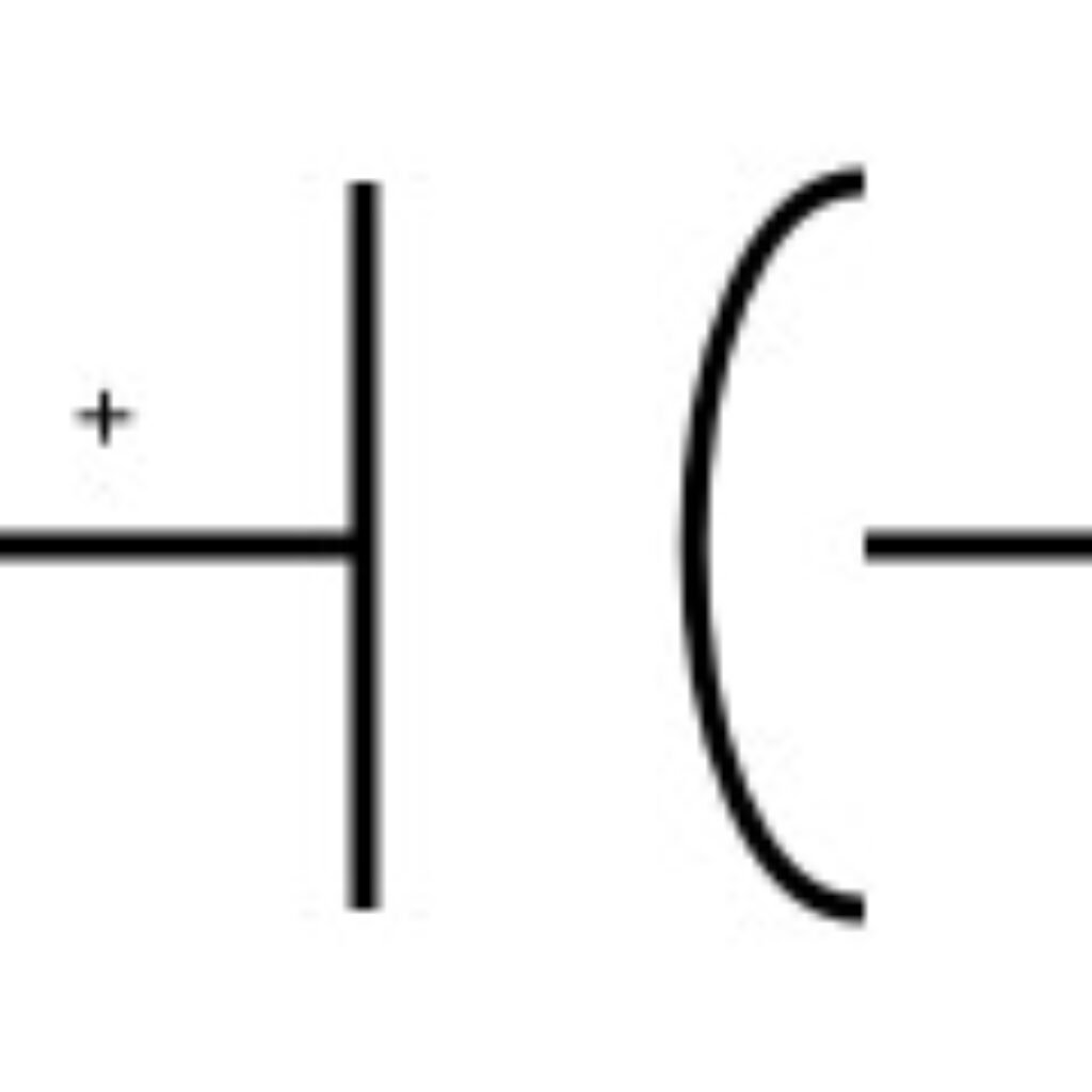 |
Polarized Electrolytic Capacitor | Yes (IEC: straight = +, curved = –) | High-µF density for power rails; observe polarity; check ripple current and voltage derating. |
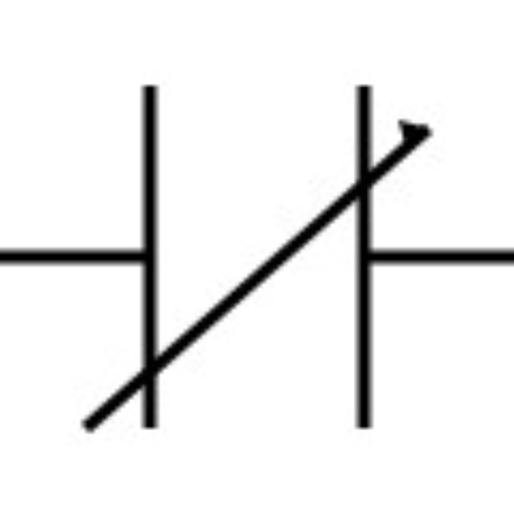 |
Variable Capacitor | No | Diagonal arrow indicates adjustability; RF tuning (LC tanks), oscillators. |
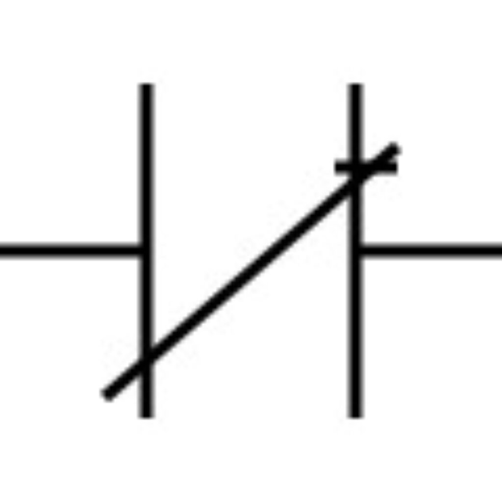 |
Trimmer Capacitor | No | Factory/field calibration; not intended for frequent user adjustments. |
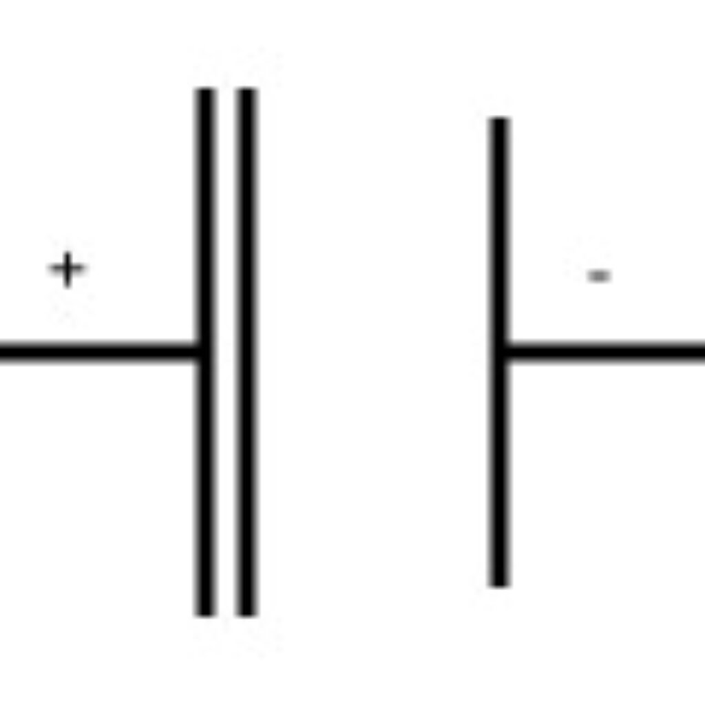 |
Supercapacitor (EDLC/Pseudo) | Usually Yes | Energy buffering/backup; fast charge/discharge. Many EDLCs are polarized—check “+/–” marks. |
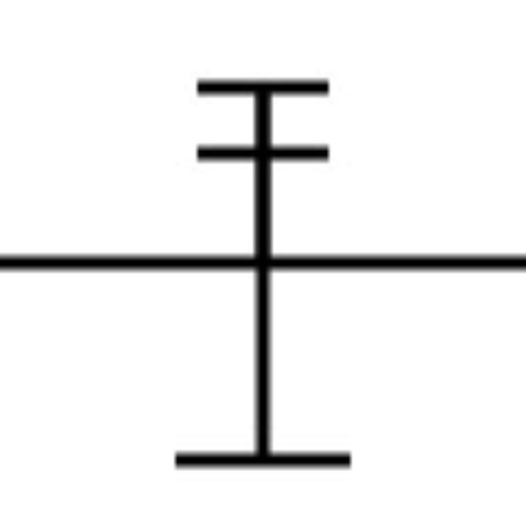 |
Feed-through Capacitor | No | EMI suppression on DC feed lines; shunts high-frequency noise to ground. |
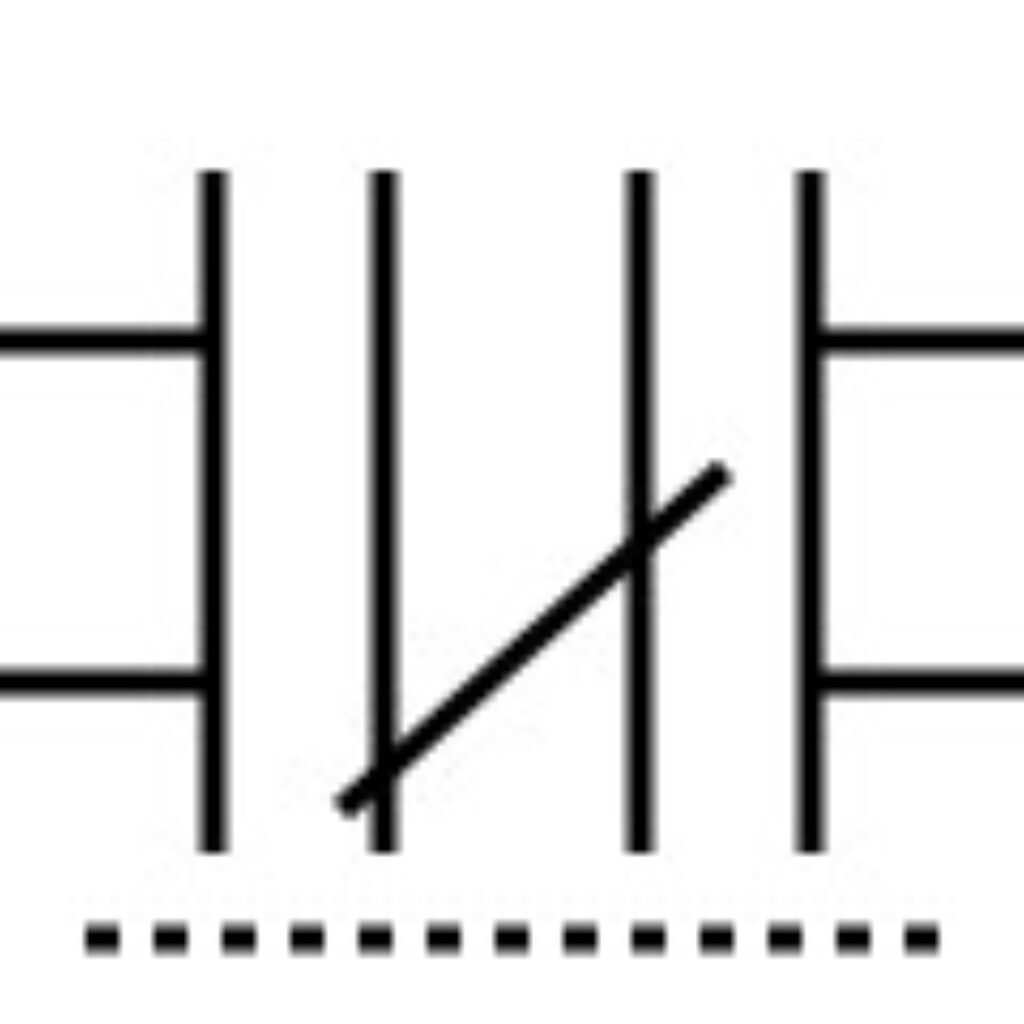 |
Differential Capacitor | No | Two sections change in opposite directions via common rotor; RF mixers/oscillators. |
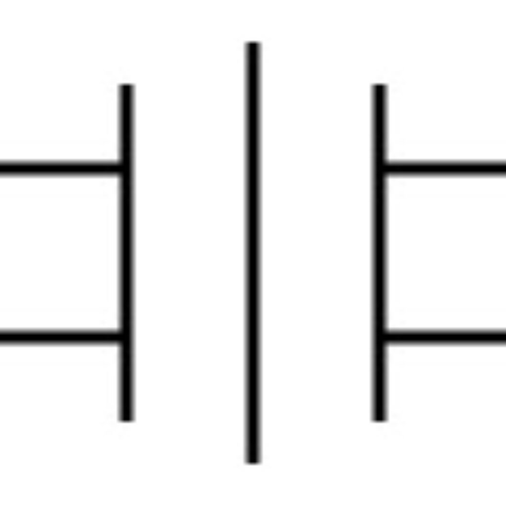 |
Split-Stator Capacitor | No | Two stators at 180° with a common rotor; improved symmetry and stability in RF tuning. |
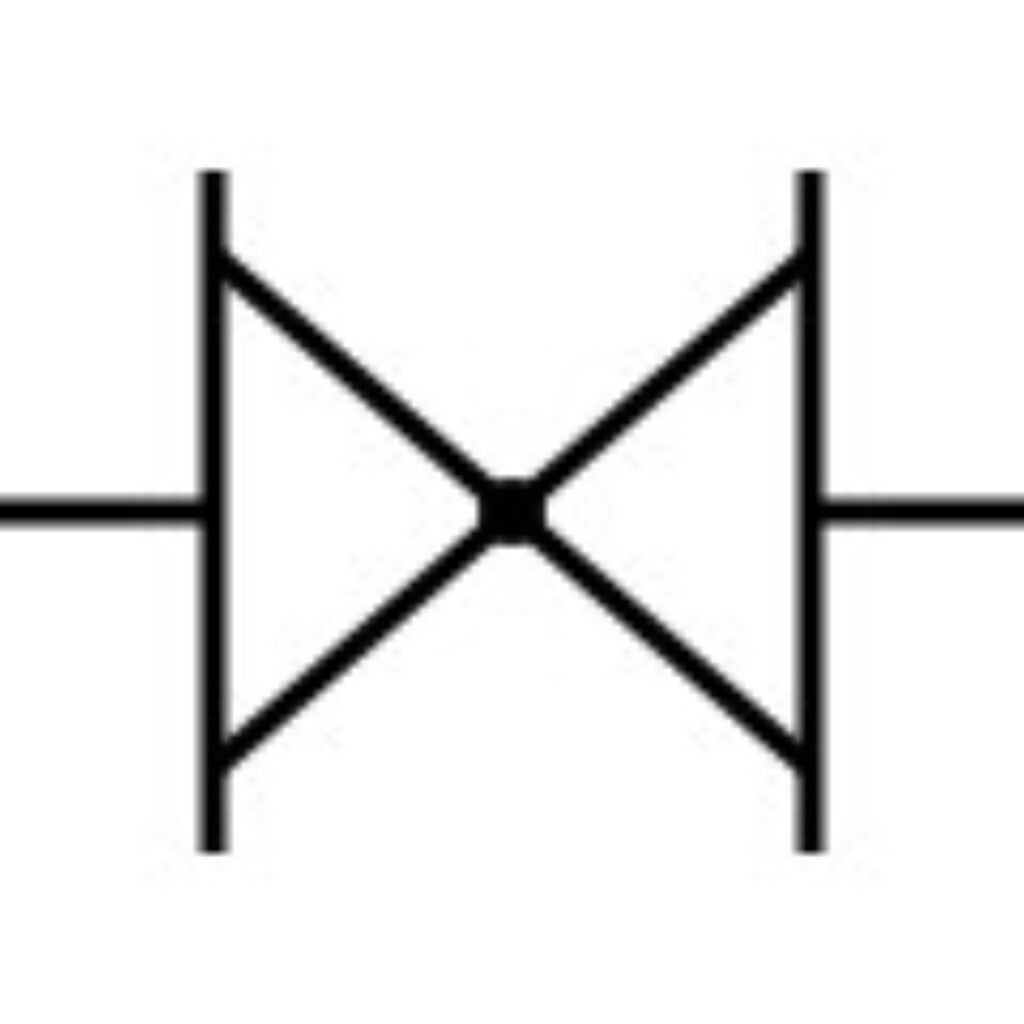 |
Butterfly Capacitor | No | Symmetrical rotor/stators (“butterfly” shape); balanced RF tuning, low loss. |
 |
Dual-Ganged Variable Capacitor | No | Two variable caps mechanically linked (one shaft); twin/two-stage tuning (e.g., radio front-ends). |
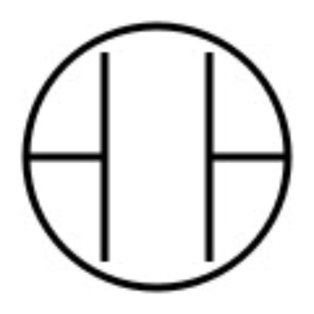 |
Vacuum Variable Capacitor | No | Variable capacitor in a vacuum envelope; high-voltage/high-power RF with very low loss. |
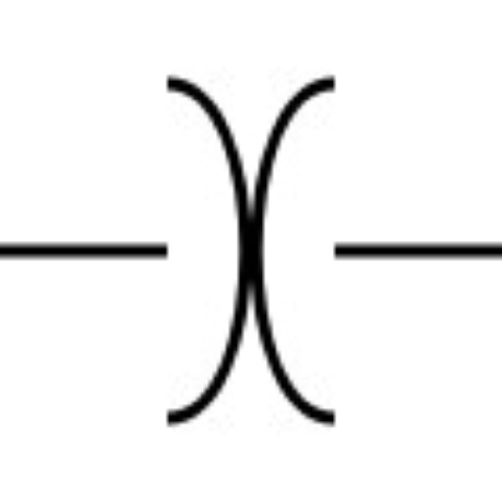 |
Bipolar (Non-polar) Electrolytic Capacitor | No | Back-to-back electrolytics for AC coupling (audio, signal paths); no polarity orientation. |
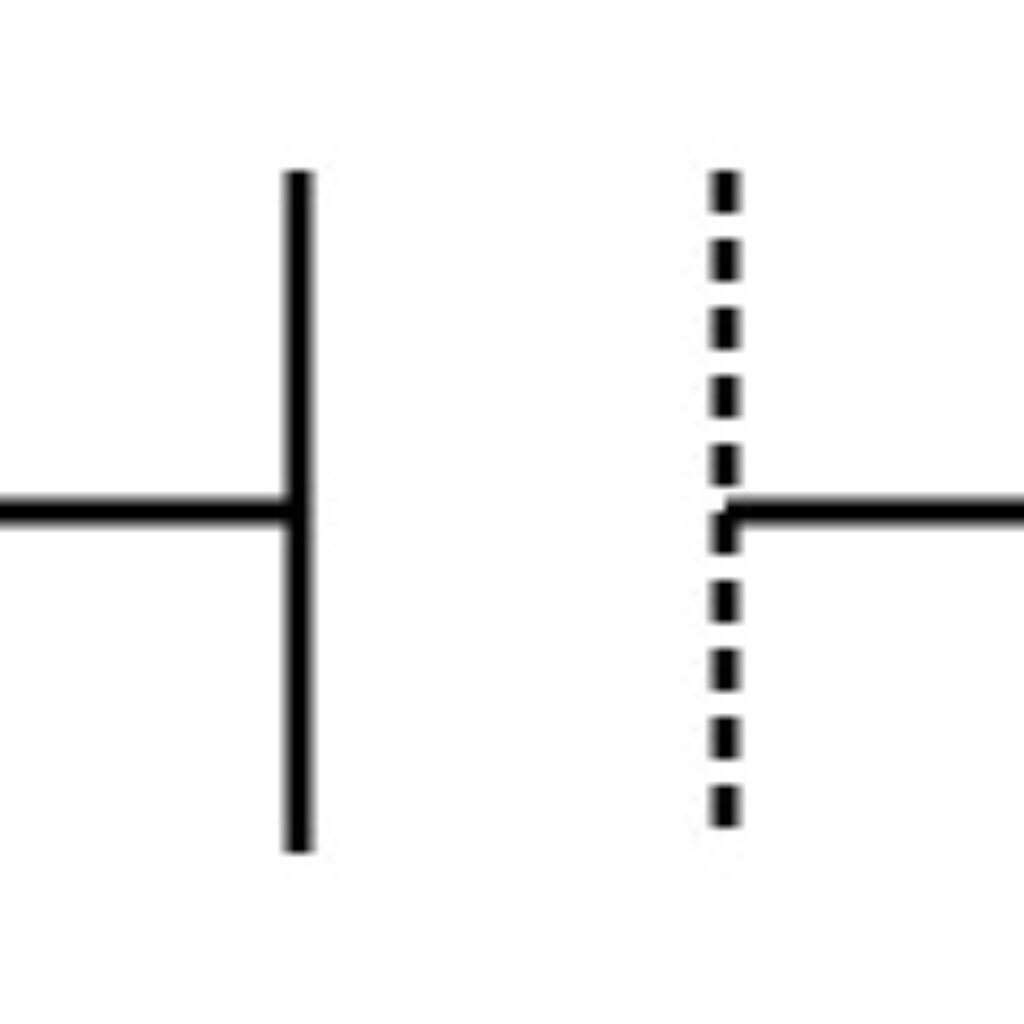 |
Film / Metallized Film Capacitor | No | Stable, low loss; timing, filtering, snubbers; metallization is a parameter, not part of the symbol. |
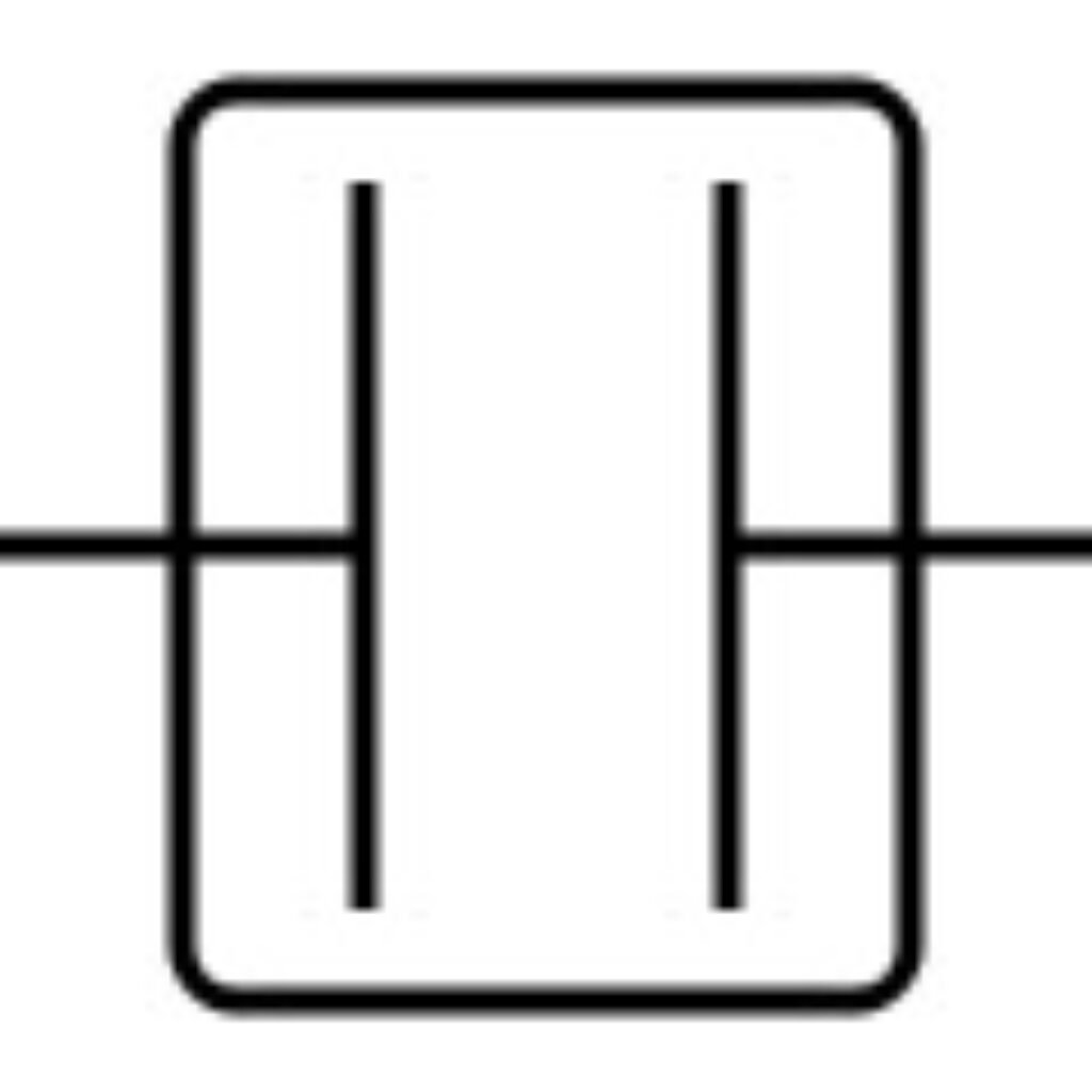 |
Motor Run / Start Capacitor | Typically No (run); verify start | Motor run caps are typically non-polar film; start caps are often non-polar electrolytics for AC duty—always confirm datasheet. |
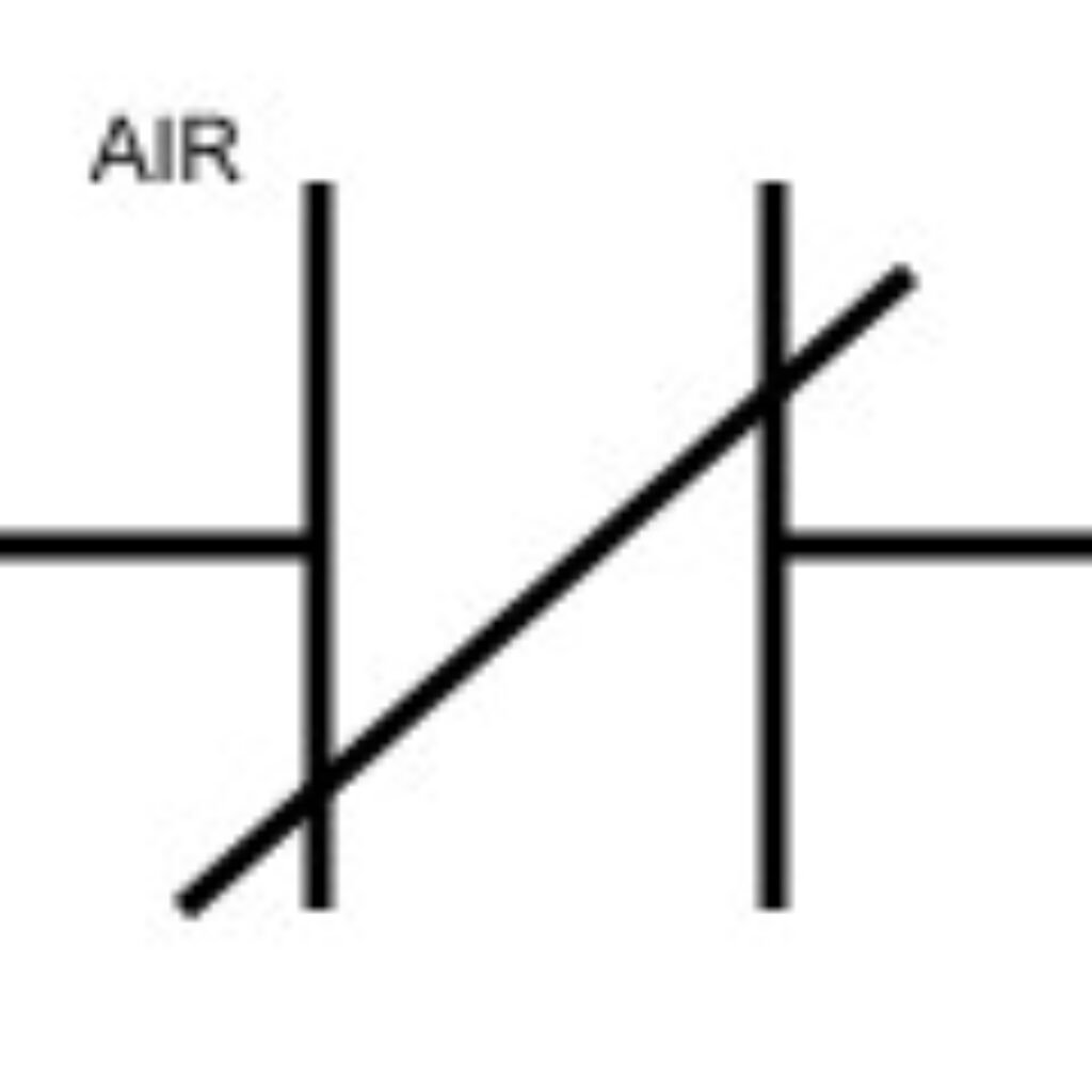 |
Variable Air-Gap Capacitor | No | Air dielectric with adjustable gap; high-frequency/high-voltage tuning applications. |
 |
Aluminum Polymer Capacitor | Yes | Polymer electrolyte version of electrolytics; low ESR, good ripple/temperature performance; observe polarity. |
Detailed Explain: Capacitor Symbols
1) Generic Capacitor — Capacitor Symbol
A generic capacitor, also called ceramic capacitor, stores energy in an electric field between two plates. This symbol represents a non-polar, fixed-value capacitor that can be connected in either direction. Some drawings show a legacy/obsolete variant for non-polar parts.
2) Polarized Electrolytic Capacitor — Capacitor Symbol
This symbol denotes a polarized capacitor that must be installed with the correct orientation. In IEC style, the straight plate is positive and the curved plate is negative. Commonly used for high-capacitance power filtering.
3) Variable Capacitor — Capacitor Symbol
A diagonal arrow across the plates indicates the capacitance is adjustable during operation. Variable capacitors are used in tuning circuits such as RF oscillators and LC filters. The symbol shows function only, not range or voltage rating.
4) Trimmer Capacitor — Capacitor Symbol
A trimmer is a small adjustable capacitor intended for factory or field calibration, not routine user adjustment. It fine-tunes filters, oscillators, and sensors. Orientation is typically non-polar unless specified by the device.
5) Supercapacitor (EDLC/Pseudo) — Capacitor Symbol
The supercapacitor symbol often shows plate styling or polarity marks to distinguish it from standard capacitors. Many EDLC types are polarized and used for energy buffering, RTC backup, and ride-through. Observe voltage and surge current limits.
6) Feed-through Capacitor — Capacitor Symbol
This symbol depicts a conductor “passing through” with a shunt path to ground. It represents a feed-through EMI filter that removes high-frequency noise from DC lines. Used in RF front ends, power entries, and shielded enclosures.
7) Differential Capacitor — Capacitor Symbol
A differential capacitor has two sections whose capacitances vary in opposite directions as a common rotor moves. It enables balanced tuning in RF mixers and oscillators. The symbol highlights the linked sections rather than values.
8) Split Stator Capacitor — Capacitor Symbol
This variable form uses two stators placed 180° apart with a common rotor. It improves symmetry and reduces hand-capacity effects in RF tuning. The symbol indicates the split structure without implying specific capacitance.
9) Butterfly Capacitor — Capacitor Symbol
The butterfly capacitor uses a symmetrical “butterfly” rotor for balanced RF tuning. It provides low loss and good linearity at high frequencies. The symbol emphasizes symmetry rather than dimensions or range.
10) Dual-Ganged Variable Capacitor — Capacitor Symbol
Two variable capacitors are mechanically linked by a single shaft so they change together. Used for multi-stage or tracked tuning (e.g., RF front ends). The symbol shows two adjustable sections under one control.
11) Vacuum Variable Capacitor — Capacitor Symbol
This symbol places a variable capacitor inside a circle to indicate a vacuum envelope. Vacuum variables handle high voltage and power with very low loss, common in transmitters and matching networks. Polarity is typically non-polar.
12) Bipolar (Non-polar) Electrolytic Capacitor — Capacitor Symbol
A bipolar electrolytic behaves like two electrolytics back-to-back, allowing AC use without polarity. It is used in audio coupling and other alternating applications. The symbol distinguishes it from standard polarized electrolytics.
13) Film / Metallized Film Capacitor — Capacitor Symbol
This non-polar symbol represents film capacitors (including metallized types). They offer stable capacitance and low loss for timing, filtering, and snubbers. Metallization and dielectric type are parameters, not shown in the glyph.
14) Motor Run / Start Capacitor — Capacitor Symbol
The symbol denotes capacitors used for motor phase shift or starting. Motor run capacitors are usually non-polar film; start capacitors are often non-polar electrolytic for short duty. Verify type, duty, and voltage from the datasheet.
15) Variable Air-Gap Capacitor — Capacitor Symbol
This variable form uses air as the dielectric with a mechanically adjustable gap. It supports high-frequency and high-voltage tuning. The symbol indicates adjustability, not the spacing or breakdown voltage.
16) Aluminum Polymer Capacitor — Capacitor Symbol
This symbol represents electrolytics with a conductive polymer electrolyte. They are typically polarized, with low ESR and strong ripple performance. Observe polarity and voltage ratings during placement and design.
Capacitor Symbol Naming Rules — Expanded Guide
A consistent naming scheme turns your symbol library from a drawing gallery into a database you can search, validate, and automate. For capacitors, the goal is to identify what the symbol means (electrical semantics) without hard-coding part numbers or ratings that will change. The four-segment pattern below keeps names short, readable, and machine-checkable.
| Segment | Code example | Meaning / Notes |
|---|---|---|
| Primary name (letter) | C | Capacitor |
| Material (letter) | A / B / C … | Dielectric / construction material |
| Type (alpha or numeric) | G / T / W / 1 / 2 … | Structure / use case |
| Serial number (number) | 01, 02, … | Distinguish size/ratings; internal increment rule |
The four-segment pattern
Primary (letter) + Material (letter) + Type (alpha/num) + Serial (number)
-
Primary: always
Cfor capacitor symbols. -
Material: one letter for the dielectric/technology (A=tantalum electrolytic, B=organic film, C=ceramic, D=aluminum electrolytic, …).
-
Type: structure or use (e.g.,
W=trimmer,T=stacked chip,J=metallized,Y=high-voltage; numeric forms like1=round,2=tube,3=stacked sealed). -
Serial: zero-padded code (01…99) to separate size/variant families within the same material+type.
Example regex:
Keeps names uniform and easy to lint in CI.
Naming principles
-
Encode semantics, not specs. The symbol name should never contain capacitance, voltage, ESR, or footprint. Put those in component fields.
-
Uppercase + hyphens.
C-C-W-07is easier to parse thanc_c_w7orCCW07. -
Zero-pad serials.
…-07sorts correctly ahead of…-12. -
One meaning = one family. If you need both IEC and ANSI polarized graphics, make two families (e.g.,
C-D-Y-01andC-D-Y-02) rather than swapping artwork. -
Document aliases. You can expose a friendlier “Display Name” (e.g., Capacitor—Ceramic Trimmer) while keeping the strict code as the Symbol ID.
Recommended field split (so symbols stay clean)
-
Symbol ID:
C-C-W-07(meaning only) -
Component fields:
Capacitance,Tolerance,Voltage,Dielectric,ESR,Ripple,TempRange,MPN,AltMPN[],Datasheet,Lifecycle,SafetyClass -
Footprint ID:
CAP_0603_METRIC1608,RADIAL_D8_P3.5, etc.
This triple (Symbol → Component → Footprint) lets you change suppliers, ratings, or packages without redrawing schematics.
Worked examples (how to read them)
-
C-C-W-07→ Capacitor, Ceramic (C), Trimmer (W), variant 07.
Use: factory calibration in filters/oscillators. -
C-A-T-05→ Capacitor, Tantalum electrolytic (A), Stacked chip (T), variant 05.
Use: dense SMD tantalum where low ESR isn’t critical. -
C-D-Y-12→ Capacitor, Aluminum electrolytic (D), High-voltage type (Y), variant 12.
Use: bulk storage on higher voltage rails. -
C-L-J-03→ Capacitor, Polyester film (L), Metallized (J), variant 03.
Use: general timing/snubber with stable film behavior. -
C-N-T-02→ Capacitor, Niobium electrolytic (N), Stacked chip (T), variant 02.
Use: tantalum alternative with similar use cases. -
C-O-G-04→ Capacitor, Glass film (O), High-power (G), variant 04.
Use: very low loss, power RF/specialty. -
C-Y-1-08→ Capacitor, Mica (Y), Round form (1), variant 08.
Use: precision RF/low-loss. -
C-B-2-06→ Capacitor, Organic film (B, e.g., polystyrene), Tube (2), variant 06.
Use: legacy precision audio/timing.
These are symbol families. The actual purchasable part is chosen by the component (with value/voltage/ESR) and then mapped to a footprint.
Conclusion
Capacitor symbols are a compact language for electrical intent, not a container for manufacturing facts. Read them for what they mean—fixed vs variable, trimmer, and especially polarity (IEC: straight plate = positive, curved plate = negative)—then rely on component fields and footprints for capacitance, voltage, ESR, dielectric class, safety rating, and package.
A disciplined library keeps this separation sharp: consistent naming, complete parameters, distinct IEC/ANSI variants, and PR-reviewed changes. On the PCB, reinforce polarity with clear “+/–” silkscreen and enlarged assembly callouts; let DRC rules enforce creepage/clearance and test-point access; include electrolytic polarity checks in AOI.
This workflow makes schematics readable, BOMs purchasable, reviews faster, and builds safer—whether you’re tuning an RF front end or stabilizing a DC rail. If you’re moving from symbol to sourcing, MOZ Electronics can help scrub your BOM, surface alternates, and align parts to your electrical and mechanical constraints. Send us your list and we’ll return a code-ready quote with vetted options—so you can ship with confidence.
Understanding Boost Converters: Principles and Applications
FAQs About Capacitor Symbols
Q1. In IEC drawings, which side is positive for a polarized capacitor?
The straight plate is positive. The curved plate indicates negative. Add explicit “+ / –” on the PCB to avoid mistakes.
Q2. Can I reuse one generic symbol for all non-polar capacitors?
Yes—provided the component parameters capture dielectric, voltage, tolerance, ESR, and footprint. Keep the symbol simple; keep the data rich.
Q3. Are trimmers the same as variable capacitors?
Both are adjustable. Trimmers are for factory/field calibration and rarely adjusted afterward. Variable capacitors are designed for regular tuning (e.g., RF).
Q4. How do I prevent reversed electrolytics on the line?
Use the triple-consistency rule, add enlarged polarity callouts on the assembly drawing, and include AOI checks specifically for electrolytics/supercaps.
Q5. What’s the easiest way to migrate from ANSI to IEC without surprises?
Pick a single house standard for new work, then add a conversion checklist for imported designs. During review, explicitly verify polarized symbols and PCB silk.


