
Ceramic Capacitors
Ceramic capacitors are the workhorse of modern electronics, providing stable, compact capacitance for everything from smartphone power rails to precision RF filters. Built from stacked ceramic dielectric layers with metallized electrodes, multilayer ceramic capacitors (MLCCs) deliver exceptional volumetric efficiency, low equivalent series inductance (ESL), and automated SMT assembly at scale. Two dielectric families define behavior: Class 1 (e.g., C0G/NP0) offers outstanding temperature stability, negligible voltage coefficient, low losses, and minimal aging—ideal for resonant circuits, oscillators, precision filters, and timing. Class 2 (e.g., X7R/X6R/X5R) maximizes capacitance in small footprints for bypass, decoupling, and coupling, with tradeoffs such as temperature drift, DC-bias-dependent capacitance, higher tan δ, and logarithmic aging.
Designers can tune performance by choosing dielectric, case size, voltage rating, and low-ESL geometries (reverse-geometry, arrays, or X2Y). Specialized ceramics address EMI/RFI suppression with X/Y safety certifications, while high-voltage doorknob/tubular formats handle RF power and laser/high-energy systems. Robust options—AEC-Q200-qualified parts, soft terminations, and extended temperature grades—support harsh environments in industrial control and automotive ECUs.
Our catalog aggregates top manufacturers (Murata, TDK, KEMET, Vishay, AVX/Kyocera, Samsung Electro-Mechanics, Yageo, Würth, Taiyo Yuden, and more) with parametric search across dielectric class, capacitance, voltage, tolerance, package, ESR/ESL, temperature rating, and safety approvals. Explore impedance curves and DC-bias charts, compare pin-for-pin alternatives, and request fast RFQs. Whether you need a C0G timing network, a low-ESL decoupling strategy for a high-speed SoC, or X2/Y2 EMI capacitors for a compact SMPS, you’ll find reliable, in-stock ceramic capacitors ready to take you from prototype to production.
Showing all 4 results
- Perfect Stability: Just ±0.3% capacitance variance across full temp range
- Micro-Scale: 0402 footprint (1mm length) ideal for wearables/IoT
- High Reliability: 500MΩ·μF minimum IR withstands harsh environments
- Ultra-Low ESR & ESL: Optimized for 100kHz+ SMPS designs
- High Capacitance Stability: Only ±15% variation (-55°C to +125°C)
- Robust Construction: "J" lead frame enhances vibration/shock resistance
- Compact & Stackable: 40% PCB space savings vs. conventional capacitors
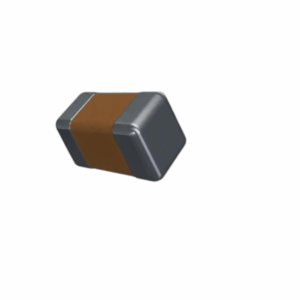
- 150°C high-temperature stability: X8R dielectric keeps capacitance within controlled variation from −55°C to +150°C, ideal for hot zones near power devices.
- Ultra-compact 0402 footprint: 1.00 × 0.50 mm size with low parasitics for effective high-frequency decoupling and EMI suppression.
- Versatile 25 V / 10 nF spec: 25 V rating with 10 nF nominal and ±20% tolerance covers common logic/analog bypassing and small RC snubber tasks.
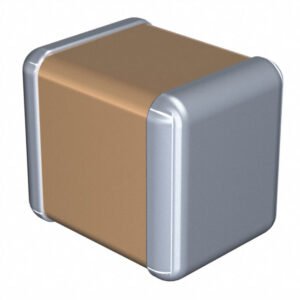
- Exceptional Temperature Stability: X8R dielectric maintains ±15% capacitance from -55°C to +150°C
- Robust Construction: Nickel barrier with tin plating for reliable solder joints
- Space-Efficient: 1210 package delivers 10μF capacity
What Is a Ceramic Capacitor?
A ceramic capacitor is a fixed-value capacitor that uses a ceramic dielectric placed between metallized electrodes. The device is formed by stacking (or shaping) ceramic layers, depositing electrodes, and connecting the alternate layers to opposite terminals. The dielectric formulation—paraelectric or ferroelectric, and its specific dopants—determines stability, losses, capacitance density, and therefore the ideal application domain. Modern multilayer ceramic capacitors (MLCCs) dominate surface-mount passives; industry output exceeds a trillion pieces annually, making them the go-to choice for decoupling, bypassing, timing, and RF circuits across consumer, industrial, medical, and automotive electronics.
Application Classes at a Glance
Ceramic capacitors are commonly grouped (per IEC and harmonized EIA practice) by dielectric behavior:
-
Class 1 (e.g., C0G/NP0, N150, N750)
Built on paraelectric dielectrics such as titanium-dioxide-based systems. They provide very high stability, near-zero voltage coefficient, low dissipation factor, and minimal aging. Typical use: precision RF tanks and filters, oscillators, PLLs, timing networks, and any circuit that benefits from tight temperature coefficient (e.g., C0G/NP0 ≈ 0 ±30 ppm/°C). -
Class 2 (e.g., X7R, X6R, X5R, X7S, Y5V, Z5U)
Ferroelectric barium-titanate mixes deliver very high permittivity and thus superb volumetric efficiency. You get far more capacitance in a smaller case size—perfect for bypass, bulk decoupling, coupling, and general filtering. Tradeoffs include non-linear voltage coefficient (DC bias effect), temperature drift, frequency-dependent capacitance, higher tan δ, and logarithmic aging (e.g., X7R ≈ 2–3% per decade).
Historically, Class 3 “barrier layer” ceramics offered even higher permittivity, but their electrical stability was poor and they are no longer standardized; Class 2 MLCCs superseded them.
MLCC Construction & Materials
An MLCC is essentially hundreds of ultra-thin ceramic sheets laminated with alternating internal electrodes, sintered into a monolithic block, and then terminated on the ends. Key process levers define performance:
-
Dielectric composition:
Paraelectric (stable, low-k) vs. ferroelectric (high-k). Tailored with oxides and dopants to hit the desired temperature characteristic (e.g., C0G, X7R, X8R). -
Layer geometry:
Capacitance scales as C=ε⋅nAdC = \varepsilon \cdot \frac{nA}{d} — increase k, area A, layer count n, and reduce thickness d. -
Electrodes:
-
NME (Noble Metal Electrodes): Ag/Pd—excellent linearity and low loss; typically used for Class 1.
-
BME (Base Metal Electrodes): Ni/Cu—cost-effective, high-volume; minor tradeoffs in voltage bias behavior; dominant for Class 2.
-
-
Terminations:
Standard Ni/Sn; soft/flex terminations add a compliant polymer layer to absorb PCB strain and reduce flex-cracking, valuable in automotive (AEC-Q200) and other high-reliability assemblies.
Package Formats & Case Codes
Ceramic capacitors ship primarily as SMD chips (MLCC) with EIA inch and IEC metric codes—e.g., 0402 (1005 metric), 0603 (1608), 0805 (2012), 1206 (3216)—down to 01005 for smartphones and wearables, and up to 2220 or larger for higher voltage/energy. Through-hole discs are still used for EMI suppression (X/Y safety capacitors), high-voltage pulse work, or legacy designs. Feedthrough and array formats combine multiple capacitive paths to save area and lower ESL.
Electrical Behavior & What It Means for Your Design
Understanding real-world characteristics ensures you pick the right dielectric and footprint.
1) Capacitance vs. Temperature
-
Class 1 (C0G/NP0): ±30 ppm/°C typical from −55 to +125 °C—practically flat.
-
Class 2: Use the EIA code:
-
X7R: −55 to +125 °C, ΔC/C ≤ ±15%
-
X6R: −55 to +105 °C, ΔC/C ≤ ±15%
-
X5R: −55 to +85 °C, ΔC/C ≤ ±15%
-
Y5V / Z5U: narrow ranges with +22/−82% or +22/−56% drift—fit only for non-critical decoupling.
-
2) DC Bias (Voltage Coefficient)
Class 2 ceramics exhibit a capacitance drop with applied DC voltage; the higher the field, the lower the effective k. A 10 µF 6.3 V X5R in 0402 can lose >50% at rated bias; larger case sizes and higher voltage ratings mitigate this. Always read the DC-bias curves and leave headroom in your capacitance budget.
3) Frequency Dependence & Resonance
Every capacitor has ESL and ESR; together with C they set a self-resonant frequency (SRF) where impedance is minimum.
-
Class 1 parts hold value better at RF and have low losses—ideal for VCOs, filters, impedance matching.
-
Class 2 MLCCs excel for HF decoupling, and in low-ESL variants (reverse geometry, long-side terminations—e.g., 0508—, array or X2Y structures), they push the SRF upward for improved high-speed digital performance.
4) Losses: ESR / tan δ / Q
-
C0G/NP0: very low tan δ (≈0.0015 or better), high Q, minimal dielectric absorption (≈0.3–0.6%).
-
X7R/X5R: higher tan δ, more dielectric absorption (≈2–2.5%), acceptable for power rails and general coupling but not for ultra-low-distortion audio filters.
5) Aging (Class 2 Only)
Ferroelectric domains relax over time—capacitance drops logarithmically (e.g., ~2–3% per decade for X7R). A solder reflow above the Curie temperature “resets” the clock. Account for initial + aging + DC-bias + tolerance to ensure minimum required C at end-of-life.
6) Insulation Resistance & Leakage
Ceramic dielectrics exhibit very high insulation resistance; leakage is typically negligible for DC hold tasks compared to electrolytics. For long hold times (sample-and-hold, precision timers) prefer Class 1.
Specialized Ceramic Families
Low-ESL / EMI-Optimized
-
Reverse-geometry MLCCs (terminals on the long edges) shorten current paths and reduce ESL, increasing SRF—great for core supply pins of FPGAs/MPUs.
-
Capacitor arrays place multiple capacitors in one body, lowering mounted inductance while saving placement time.
-
X2Y® structures add internal shield electrodes, simultaneously providing line-to-line and line-to-ground capacitance—excellent for noise suppression and EMC compliance with fewer parts.
Safety-Rated EMI/RFI Suppression (X/Y)
X-class devices connect across the line (differential-mode); Y-class connect line-to-ground (common-mode). Certified to IEC/EN 60384-14 and relevant UL/CSA/CQC standards, they are designed to fail safely under surges and long-term mains stress. You’ll find them as leaded discs and increasingly as SMD safety MLCCs for compact SMPS filters.
High-Voltage / Power Ceramics
Large disc, doorknob, tubular, or pot-style power ceramics handle kilovolt ratings and RF power with low losses—used in transmitters, induction heaters, laser HV supplies, PFC, multipliers, and pulse shaping. Some versions accept water cooling. For precision RF tanks, Class 1 power ceramics (low tan δ) are still the benchmark.
Reliability, Robustness & Assembly
-
Flex cracking is the primary MLCC failure mode on rigid boards. Mitigations: soft terminations, keep-out zones, correct pad sizes, symmetrical reflow profiles, controlled depanelization, and minimizing connector-induced bending.
-
Thermal & mechanical stress can change parameters; allow 24-hour recovery after reflow before acceptance testing.
-
Automotive/AEC-Q200 MLCCs feature extended testing (temperature cycling, bias humidity, vibration) and documentation suitable for safety goals.
Typical Ceramic Capacitors Application & How to Select A Right Ceramic Capacitor
A) Microcontroller/Processor Rails
-
Goal: low impedance across a wide band.
-
Pick: Many small-case X7R/X5R MLCCs located close to pins + a few reverse-geometry or arrays to push SRF higher. Add one or two bulk ceramics (10–47 µF) in larger case sizes and voltage ratings to combat DC-bias loss.
-
Tip: Use power-integrity tools or simple target-impedance calculations; distribute values (0.01–10 µF) to cover decades of frequency.
B) RF & Timing
-
Goal: stability, low loss, predictable reactance.
-
Pick: C0G/NP0 only; specify tight tolerance (E24/E48/E96) and verify Q at your operating frequency.
-
Tip: Keep traces short; place at ground-referenced microstrip/CPW discontinuities carefully.
C) Audio & Precision Analog
-
Goal: low dielectric absorption, minimal voltage coefficient.
-
Pick: C0G/NP0 for filters and integrators; use Class 2 only for noncritical decoupling.
D) HV or Mains EMI
-
Goal: safety and endurance under surge.
-
Pick: X1/X2 or Y1/Y2 certified ceramics sized for dv/dt and ripple current; respect creepage/clearance and flame-retardant requirements.
E) Harsh/Automotive
-
Goal: long life over −40…+125/150 °C, vibration, humidity.
-
Pick: AEC-Q200 MLCCs, soft terminations, conservative DC bias (use higher voltage rating or larger case), and derate temperature/current.
Popular Ceramic Capacitors Manufacturers & Series
We source and support leading Ceramic Capacitors from Murata, TDK/EPCOS, KEMET, Vishay, Samsung Electro-Mechanics, AVX/Kyocera, Yageo/Phycomp, Würth Elektronik, Taiyo Yuden, Nichicon, Panasonic, Johanson, and others—across C0G/NP0 precision parts, high-capacitance X7R/X5R MLCCs up to 100 µF, low-ESL arrays, safety-rated X/Y ceramics, and high-voltage discs.
Why Buy Ceramic Capacitors From MOZ Electronics?
-
Deep parametric filters (dielectric, EIA code, capacitance, voltage, case size, tolerance, temp range, ESR/ESL, AEC-Q200, safety class).
-
Datasheets & models: S-parameters, SPICE, impedance plots, DC-bias curves where available.
-
Design support: drop-in alternatives, DC-bias headroom guidance, PI/EMI recommendations.
-
Procurement: real-time stock, lifecycle status, and quick RFQ from prototypes to volume.