In precision optics, photonics, and low-light detection, signal levels are often so small that even a pristine voltage amplifier struggles to lift them above the noise floor. That’s where a transimpedance amplifier (TIA) earns its keep. By converting sensor current—most commonly from a photodiode—directly into a proportional voltage, a TIA gives you deterministic gain, predictable noise behavior, and a clean path into scopes, lock-ins, and data-acquisition systems.
Among compact, lab-friendly TIAs, Thorlabs’ AMP100 stands out for its simplicity and its focus on low-frequency, high-sensitivity work. This article pulls together a practical, lab-oriented overview of the AMP100: what it is, how it works, where it excels, how to set it up, and how it compares with sibling models. If you work with dim light, slow optical signals, or need a drop-in preamp for a photodiode, this guide is for you.
Meet the AMP100
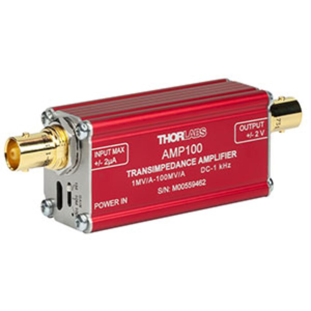
The AMP100 is a compact, inline, BNC-to-BNC TIA powered by 5 V over Micro-USB. It’s designed for low-frequency (DC to ~1 kHz), low-noise measurements with switchable gains of 1 MΩ, 10 MΩ, and 100 MΩ (equivalently 1, 10, and 100 MV/A). A polarity switch supports both anode-grounded and cathode-grounded photodiode wiring. A zero-adjust knob lets you null out dark current or tiny offsets so your baseline sits where you want it.
At a glance
- Transimpedance gains: 1, 10, 100 MΩ
- Bandwidth (–3 dB): DC to ~1 kHz
- Rise/fall time: < 300 µs
- Max input current (per range): ±2 µA (1 MΩ), ±200 nA (10 MΩ), ±20 nA (100 MΩ)
- Max output voltage: ±1.0 V into 50 Ω, ±2.0 V into Hi-Z
- Output impedance: 50 Ω
- Power: 5 V via Micro-USB (supply/cable included)
- Size & weight: ~97 × 32 × 25.4 mm; ~80 g
- Mounting: compatible with ECM100/ECM125/EPS125 clamps
- Use case: low-frequency, high-sensitivity photodiode measurements
In short: it’s a bench-friendly preamp that you can stick right between a photodiode and your instrument, flip a couple of switches, and get on with the experiment.
Why the bandwidth limit is a feature (for the right jobs)
A 1 kHz (–3 dB) bandwidth is not a limitation for many optical experiments—it’s a form of analog anti-aliasing and noise-bandwidth control. When you’re integrating over milliseconds to seconds, higher bandwidth only invites more noise and environmental pickup. For fluorescence, slow laser power drifts, or steady low-light monitoring, the AMP100’s bandwidth is well matched to the physics.
If you do need more speed (kHz–MHz), you’ll want a different tool. Thorlabs offers higher-bandwidth models (covered later) that trade gain for speed.
Understanding the ranges (with concrete numbers)
Because a TIA’s output is I×RfI \times R_fI×Rf, it’s useful to translate typical photodiode currents into volts to pick the right gain:
- 1 MΩ range (±2 µA):
- 1 nA → 1 mV
- 100 nA → 0.1 V
- 1 µA → 1 V
- Good for brighter signals or when you need more headroom.
- 10 MΩ range (±200 nA):
- 1 nA → 10 mV
- 10 nA → 0.1 V
- 100 nA → 1 V
- A sweet spot for modest low-light levels.
- 100 MΩ range (±20 nA):
- 100 pA → 10 mV
- 1 nA → 0.1 V
- 10 nA → 1 V
- Best for the dimmest signals—but watch the input limit.
Remember the output limits: ±1 V into a 50 Ω instrument (e.g., when your oscilloscope input is 50 Ω terminated) or ±2 V into a high-impedance input (1 MΩ scope input, DAQ, or lock-in). If you see clipping, reduce RfR_fRf or the optical power, or remove the 50 Ω termination.
Controls and connectors
- BNC-F input / BNC-F output: Inline and robust for lab use.
- Gain switch: Select 1 MΩ, 10 MΩ, or 100 MΩ.
- Polarity switch: Flip to match your photodiode grounding (AG vs CG).
- Zero adjust: Gently dial out dark current and offsets to park the baseline.
- Micro-USB power: Keeps the box tiny and portable; the included 5 V supply minimizes ground-loop surprises.
Quick-start: from dark table to clean trace in minutes
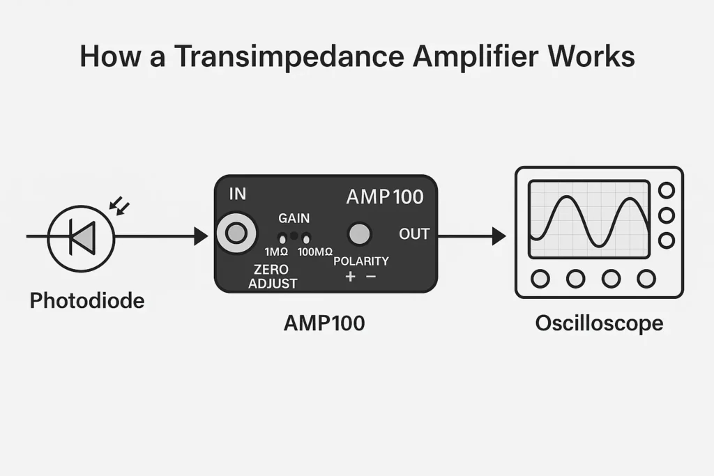
- Wire the photodiode correctly.
Decide whether your diode’s anode or cathode is grounded; set the AMP100’s polarity accordingly. Use short, shielded cables and keep the TIA close to the sensor to minimize stray capacitance. - Set a conservative gain.
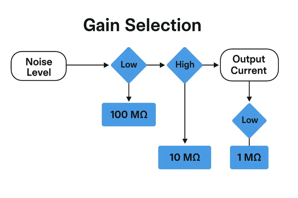
Start at 1 MΩ if you don’t know the signal level. You can increase to 10 MΩ or 100 MΩ once you see the scale. - Choose the right instrument input.
For maximum swing, use a high-impedance (1 MΩ) scope input or your DAQ’s high-Z channel. Use 50 Ω only when you specifically need impedance matching—note you’ll halve the available output swing. - Kill the lights (or cap the diode).
With the photodiode dark, tweak zero adjust until the readout sits near 0 V. Don’t chase perfection; remove only the static offset so you retain dynamic range for the signal. - Bring in the optical signal.
Increase optical power slowly while watching for saturation (flat-topped waveform, clipped plateaus). If you clip, back down the light or step to a lower gain. - Log or view.
At low frequencies, average or low-pass filtering on your instrument can further improve SNR. For multi-second integrations, consider oversampling and digital averaging.
Noise and stability in practice
You won’t find a TIA that breaks the gain–bandwidth–noise triangle; you can only pick where you want to live. The AMP100 chooses high transimpedance and modest bandwidth, which helps in three ways:
- Lower integrated noise: The 1 kHz ceiling constrains noise bandwidth.
- Reduced pickup: Less sensitivity to mains hum and mechanical microphonics.
- Predictable baselines: The zero control helps null out dark current, so baselines drift less in long runs.
A few pragmatic tips to push performance:
- Minimize photodiode capacitance. Smaller area diodes and reverse bias reduce CdC_dCd, improving stability with high RfR_fRf.
- Short cables, good shielding. The input node is sensitive; treat it gently.
- Avoid ground loops. Power the AMP100 with the included adapter, and keep your measurement system’s ground layout tidy.
Applications that play to AMP100’s strengths
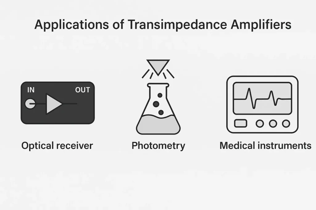
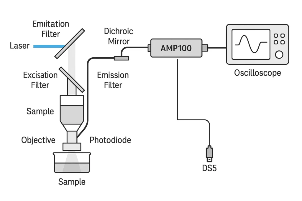
- Fluorescence and chemiluminescence: Slow, dim signals benefit from high transimpedance and low noise bandwidth.
- Laser power monitoring / drift tracking: DC to sub-kHz variations are captured cleanly; use 1 MΩ or 10 MΩ depending on the photodiode current.
- Spectroscopy at low light: When scan speeds are slow and signals small, 10–100 MΩ ranges shine.
- Educational optical comms and modulation demos: Despite the 1 kHz limit, many classroom-scale experiments run in the tens to hundreds of hertz.
- Preconditioning for ADCs and lock-ins: Set gain so your signal uses most of the ±1–2 V output range; the TIA becomes a clean front end.
Advantages you’ll notice on the bench
- Three gains, one box: Easy range selection without swapping hardware.
- Compact inline format: Lives right in your BNC chain; no rack space or bench clutter.
- USB power: Zero-hassle deployment; no ±15 V bricks.
- Polarity switch: No re-wiring gymnastics when you swap diode configurations.
- Zero adjust: Baseline control without resorting to digital post-processing.
- Low-frequency stability: A well-behaved, “quiet” amplifier for long integrations.
Limitations to keep in mind
- Speed: The –3 dB point at ~1 kHz is deliberate but disqualifies high-speed photodiode work.
- Dynamic range at high gain: At 100 MΩ you’re limited to ±20 nA—easy to exceed if stray light creeps in.
- Output swing vs termination: You get ±1 V into 50 Ω; choose Hi-Z when you need more headroom.
- Cost vs DIY: You can build an op-amp TIA for less, but you’ll spend time on layout, stability, and power. The AMP100 buys you time and predictability.
Choosing between AMP100 and related Thorlabs models
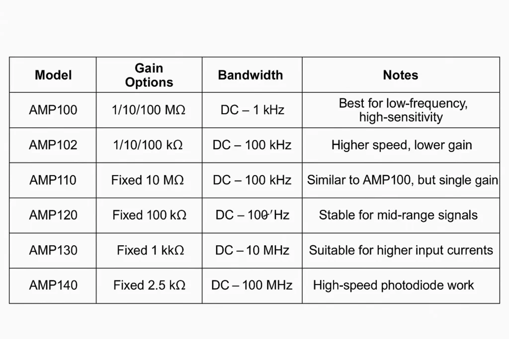
Thorlabs’ lineup spans different gain–bandwidth points. A simplified decision guide:
| Model | Transimpedance Options | Bandwidth (–3 dB) | Where it fits |
|---|---|---|---|
| AMP100 | 1/10/100 MΩ | DC–1 kHz | Best for low-frequency, very low light; flexible gain, zero adjust |
| AMP110 | 10 MΩ (fixed) | DC–1 kHz | Like AMP100’s mid range but simpler; choose for set-and-forget rigs |
| AMP102 | 1/10/100 kΩ | DC–100 kHz | Faster, lower gain; good for brighter signals with sub-MHz content |
| AMP120 | 100 kΩ (fixed) | DC–100 kHz | Stable for moderate currents and modest speed |
| AMP130 | 1 kΩ (fixed) | DC–100 kHz | High-current photodiodes; low gain, keeps headroom |
| AMP140 | 10 kΩ (fixed) | DC–10 MHz | High-speed work; pairs with small-capacitance diodes |
| AMP145 | 2.5 kΩ (fixed) | DC–100 MHz | Extremely fast detection; specialized high-speed optics |
Use this table as a first pass: pick bandwidth for your physics, then choose the transimpedance that gives a comfortable voltage swing without hitting current limits.
Integrating the AMP100 into real systems
With an oscilloscope
- Prefer 1 MΩ input to access ±2 V swing.
- If you must use 50 Ω (for cable matching), expect the ±1 V cap and set gain accordingly.
- Leverage averaging or low-pass filters for steady signals.
With a lock-in amplifier
- The AMP100’s low bandwidth is a good match to low modulation frequencies (tens to hundreds of Hz).
- Set the lock-in’s input to Hi-Z.
- Choose modulation frequency well below 1 kHz to avoid phase roll-off at the TIA.
With a DAQ/ADC
- Verify input impedance (usually high) and full-scale range; set TIA gain so your signal occupies ~60–90% of range.
- Sample above Nyquist with a comfortable margin relative to your signal bandwidth; apply digital averaging if needed.
Safety, reliability, and good habits
- Protect the input: The TIA expects micro- to nanoampere currents. Avoid connecting sources that can deliver milliamps or static surges. Use dust caps and handle photodiodes with ESD care.
- Mind reverse bias: Reverse-biased diodes improve speed and linearity but can increase dark current; ensure your diode biasing scheme is compatible with the AMP100 and your polarity choice.
- Thermal drift: Let the system warm up for a few minutes before zeroing; re-touch the zero if your ambient changes significantly during long runs.
- Cable discipline: Keep the photodiode-to-AMP100 cable short and shielded; route away from power lines and galvo drivers.
Example: sizing gain for a fluorescence rig
Suppose your photodiode produces 2 nA at peak fluorescence. You want ~1 V full-scale into a high-impedance DAQ.
- At 1 MΩ, V=2nA×1MΩ=2mVV = 2 \text{nA} \times 1 \text{MΩ} = 2 \text{mV}V=2nA×1MΩ=2mV → too small.
- At 10 MΩ, V=20mVV = 20 \text{mV}V=20mV → visible, but modest.
- At 100 MΩ, V=0.2VV = 0.2 \text{V}V=0.2V → solid headroom and SNR.
If your background/dark current is ~0.5 nA, the 100 MΩ range yields a 50 mV DC offset—easy to null with zero adjust so your DAQ can zoom in around zero. Just ensure the 2 nA signal plus any drifts stays well under the ±20 nA input limit.
Buying and practicalities
- Price (2025): ≈ USD 575.56
- What’s in the box: AMP100, 5 V USB power supply, ~1.5 m cable
- Mounting: Optional ECM/EPS clamps and adapter cables available
- Availability: Typically stock with fast shipping via Thorlabs and distributors
While a hand-rolled TIA can be cheaper, the AMP100’s value is its time-to-results: no PCB spins, no oscillations to tame, no power-supply hunt, and consistent behavior across labs and users.
Frequently asked questions
Q: Can I use the AMP100 for pulse measurements?
A: Yes, if your pulse content lives comfortably below ~1 kHz in spectral terms (e.g., millisecond-scale pulses). For microsecond pulses or MHz content, use a higher-bandwidth TIA (e.g., AMP140/AMP145).
Q: Does the zero adjust remove noise?
A: No—it cancels static offset (e.g., dark current), not random noise. It’s a baseline trim so you can use your dynamic range efficiently.
Q: Should I terminate the output with 50 Ω?
A: Only if you need impedance matching for long coax runs at higher frequencies. Otherwise, prefer a high-impedance input to access the full ±2 V swing.
Q: How do I avoid oscillations with high RfR_fRf?
A: Keep input capacitance low (small photodiode area, short cables, careful wiring). The AMP100’s internal compensation targets stability over its specified bandwidth, but good cabling practice still matters.
Conclusion
The AMP100 is a purpose-built TIA for low-frequency, low-light optical work. Its three selectable gains, polarity flexibility, and zero-offset control let you dial in sensitivity without fuss. If your experiment lives at DC to ~1 kHz—fluorescence assays, slow power monitoring, dim spectroscopy, educational modulation demos—the AMP100 will feel like a natural extension of your photodiode.
If you need more speed, its siblings (AMP102/120/140/145) cover the higher-bandwidth ground. But for quiet, reliable, bench-friendly measurements at the faint end of the light scale, the AMP100 earns its place in the toolkit—compact in size, generous in utility, and optimized for exactly the jobs most voltage amps fumble.


