

LP-MSPM0C1104 TI LP-MSPM0C1104 LaunchPad for 24-MHz Arm® Cortex®-M0+ MCU
- All-in-one USB — single cable for power, flashing, debug, and backchannel UART.
- Instant I/O — built-in red LED and user button for immediate bring-up and demos.
- BoosterPack-ready — standard 20-pin headers to snap in sensors, radios, and displays fast.
Texas Instruments LP-MSPM0C1104 LaunchPad Development Kit Overview
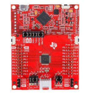
The Texas Instruments LP-MSPM0C1104 LaunchPad™ development kit is a compact, low-cost evaluation module (EVM) that gets you productive on the MSPM0C1104 Arm® Cortex®-M0+ microcontroller in minutes. Designed for learning, prototyping, and accelerating time-to-first-blink through to application bring-up, it combines a production-grade on-board debug probe, simple user I/O, and TI’s popular BoosterPack™ ecosystem into a neat, USB-powered board.
At the heart of the kit is the MSPM0C1104 MCU—a 24-MHz Cortex-M0+ with 16KB Flash and 1KB SRAM—paired with an integrated 12-bit SAR ADC capable of up to 866 ksps across 10 external channels. This balance of performance, precision analog, and ultra-low power makes the device a strong fit for sensing, metering, and control nodes. For developers, the LaunchPad exposes the MCU’s key pins on standard 20-pin BoosterPack headers, enabling rapid add-on of wireless connectivity, displays, sensors, motor drivers, and more—either from your own BoosterPack design or the vast catalog from TI and third-party partners.
Debug and programming are seamless thanks to the onboard XDS110 debug probe, which provides full device programming/debugging plus a convenient backchannel UART over the single USB connection. Out of the box, the board ships pre-programmed with an example you can drive from a simple GUI; from there you can flash your own firmware and even run the board stand-alone from external power (3.3 V or 5 V rails—never both at once). Typical development flows include Code Composer Studio™ (CCS) on Windows®, macOS®, or Linux®, or CCS Cloud directly in the browser without installing desktop software.
In addition to the MCU and debugger, TI thoughtfully integrates board-level components to improve robustness and signal integrity. An RC filter is provided for cleaner ADC measurements or for shaping a PWM-based DAC output. ESD protection on the USB interface helps safeguard your setup during development, while a precision voltage reference supports the XDS110 circuitry for reliable debug sessions. For quick interaction, the board includes one user pushbutton and one red LED—the essentials needed to validate toolchains, confirm pin muxing, or build quick demos.
Whether you are evaluating MSPM0 for the first time or moving an existing design toward production, LP-MSPM0C1104 offers a fast, friendly path from idea to proof-of-concept across applications such as battery charging and management, power supplies, building security, fire safety, printers and peripherals, grid infrastructure, smart metering, communications modules, medical/healthcare devices, and lighting. With tight CCS integration, USB-powered convenience, and BoosterPack expansion, it’s the straightest line to results on the MSPM0C110x platform.
Key Specifications
| Parameter | Value |
|---|---|
| Product name | LP-MSPM0C1104 LaunchPad™ development kit |
| Target MCU | MSPM0C1104 (Arm® Cortex®-M0+ up to 24 MHz) |
| Program memory / SRAM | 16 KB Flash / 1 KB RAM |
| Analog front end | 12-bit SAR ADC, up to 866 ksps, 10 external channels |
| On-board debugger | XDS110 debug probe (programming & full debug) |
| Data link | Backchannel UART via USB (virtual COM port) |
| Power options | USB-powered; or external 3.3 V or 5 V rails (use only one; do not apply both simultaneously) |
| User interface | 1× user pushbutton, 1× red LED |
| Expansion | 20-pin BoosterPack™ headers (compatible with many TI/3rd-party BoosterPacks) |
| Analog helper | RC filter for ADC input conditioning or PWM-to-DAC output smoothing |
| Development tools | Code Composer Studio™ (CCS) for Windows/macOS/Linux; CCS Cloud in a browser (no install) |
| Out-of-box experience | Factory example preloaded; controllable via a simple GUI |
| Post-flash operation | Can run stand-alone from external supply (3.3 V or 5 V rails) |
| USB protection | TPD4E004 ESD protection array on USB lines |
| Board regulation | TPS73533 3.3-V LDO regulator (for XDS110 and target power) |
| Debug reference | LM4040C25 precision shunt voltage reference (XDS110 circuitry) |
| Debug host device | MSP432E401Y MCU used on-board to implement XDS110 |
| Included target device | MSPM0C1104SDGSR evaluation device populated on board |
| Typical applications | Battery management, power delivery, printers/peripherals, building security, fire safety, grid, metering, comms modules, medical, lighting |
| Form factor | Compact LaunchPad board; small bench footprint |
| Connectivity to PC | Single USB cable for power, programming, debug, and UART |
| Operating systems | Works with CCS on Windows®, macOS®, Linux® |
Detailed Description
MSPM0C1104 MCU at the core. The board showcases TI’s MSPM0C1104—a cost-effective, low-power M0+ device tuned for mixed-signal control and sensing. With 24-MHz CPU speed, 16 KB Flash, and 1 KB SRAM, it’s sized for compact applications while still supporting robust real-time control loops, communication stacks for peripherals, and data-acquisition tasks. The integrated 12-bit SAR ADC reaches up to 866 ksps and exposes 10 external channels, giving you the resolution and throughput to digitize sensors, monitor rails, or implement closed-loop control without external converters.
Production-grade debug on board. The integrated XDS110 debug probe eliminates external emulators and extra cables. You can program flash, set breakpoints, inspect memory, and single-step code directly from CCS—all over a single USB connection. The backchannel UART piggybacks on that same cable, so you can stream logs, expose a CLI, or visualize sensor values without extra adapters.
Effortless power and I/O. Connect the board to your PC and it powers from USB—simple. When you’re ready to cut the cord, you can power the board from an external 3.3 V or 5 V rail (choose one; never apply both simultaneously). For quick I/O validation, the user button and red LED are ready for heartbeat tasks, debounced inputs, timing checks, or demo UX. The included RC filter helps you prototype cleaner ADC inputs or convert a PWM to a low-ripple analog level (PWM-DAC) without grabbing extra parts.
BoosterPack ecosystem for rapid feature add-ons. With 20-pin BoosterPack headers, you can click in a wide range of add-on boards—wireless modules (BLE, Sub-1 GHz), graphical LCDs, environmental sensors, motor drivers, keypads, and more. This modular approach lets you validate interfaces and features in hours, not days, and quickly benchmark whether MSPM0C1104 meets your application needs before you commit to a custom PCB.
Software that fits your workflow. Use Code Composer Studio™ locally on Windows®, macOS®, or Linux®, or dive in via CCS Cloud for a zero-install path right in your browser. The LaunchPad ships pre-loaded with an example you can control through a GUI, perfect for sanity checks of your toolchain and USB drivers. From there, create a new CCS project, import TI examples, or start from scratch with your preferred HAL/driver style.
Robust board design for daily development. TI incorporates TPD4E004 ESD protection on the USB data lines to help prevent port damage in the lab. A TPS73533 LDO generates a clean 3.3-V rail for the debugger and target device, while an LM4040C25 precision reference supports the XDS110’s analog stability. The XDS110 itself is implemented using an MSP432E401Y—a powerful Cortex-M4F MCU with Ethernet, CAN, 1 MB Flash, and 256 KB RAM—ensuring reliable, responsive debug sessions day in and day out.
From first blink to field-ready prototype. Start by confirming your toolchain with a blinking LED and button interrupt demo. Next, plug in an environmental-sensor BoosterPack and stream ADC readings through backchannel UART to a Python plot on your host. Graduate to power-supply telemetry or battery-charge control by sampling voltages and currents with the 12-bit ADC, leveraging timers for PWM control. When your firmware is ready, flash it once and run stand-alone from your own regulated supply—ideal for in-situ tests where a PC connection is inconvenient.
Applications
-
Battery charging & management: Monitor pack voltages and thermistors, implement charge profiles, and log events via UART.
-
Power supplies & power delivery: Sample rails with the 12-bit ADC, close the loop with PWM control, and validate protections.
-
Personal electronics & connected peripherals: Build input devices or printer submodules with compact code and low power.
-
Building security & fire safety: Read detectors and contact sensors, debounce inputs, and implement alarm logic.
-
Grid infrastructure & smart metering: Acquire analog signals (current shunts, voltage dividers) and process locally.
-
Communication modules: Use UART/SPI/I²C to bridge sensors or radios to host systems.
-
Medical & healthcare (non-diagnostic prototypes): Evaluate simple patient-adjacent sensing nodes and user feedback.
-
Lighting: Prototype LED dimming and driver control with PWM plus ADC monitoring.
Three Small but Mighty Highlights
-
All-in-one USB — single cable for power, flashing, debug, and backchannel UART.
-
Instant I/O — built-in red LED and user button for immediate bring-up and demos.
-
BoosterPack-ready — standard 20-pin headers to snap in sensors, radios, and displays fast.
Specifications
| Parameter | Value |
|---|---|
| MCU core | Arm® Cortex®-M0+, up to 24 MHz |
| Flash / RAM | 16 KB / 1 KB |
| ADC | 12-bit SAR, up to 866 ksps, 10 external channels |
| Debug interface | Onboard XDS110 (SWD/JTAG as applicable for MSPM0C1104), backchannel UART |
| Power input | USB 5 V; external 3.3 V or 5 V rails (use only one at a time) |
| User controls | 1× pushbutton (user) |
| Indicators | 1× red LED (user) |
| Analog conditioning | RC filter for ADC input or PWM-DAC output |
| Expansion | Dual 20-pin BoosterPack headers (signal and power breakout) |
| Protection & regulation | TPD4E004 (USB ESD), TPS73533 (3.3-V LDO Regulator), LM4040C25 (precision reference) |
| Debugger host MCU | MSP432E401Y (Cortex-M4F) implementing XDS110 |
| Supplied target device | MSPM0C1104SDGSR on board |
| Development tools | Code Composer Studio (desktop) and CCS Cloud (browser-based) |
| Operating systems | Windows®, macOS®, Linux® |
| Typical use cases | Sensing, control, metering, interface bridging, education & training |
Why Choose LP-MSPM0C1104?
-
Fast ramp-up: Pre-flashed example and CCS/Cloud support mean you can verify toolchains and run first code immediately.
-
Accurate mixed-signal evaluation: The 12-bit ADC, helpful RC filter, and clean power let you assess signal chains credibly.
-
Scalable prototyping: BoosterPack headers keep your design modular while you validate features and interfaces.
-
Robust day-to-day lab use: ESD protection, regulated rails, and a proven XDS110 implementation prioritize reliability.
Specification: TI LP-MSPM0C1104 LaunchPad for 24-MHz Arm® Cortex®-M0+ MCU
|
User Reviews
Only logged in customers who have purchased this product may leave a review.
Related Products


There are no reviews yet.