
 1")
C1005x8R1E103M050BA TDK C1005x8R1E103M050BA MLCC – 10nF 25V X8R (0402)
- 150°C high-temperature stability: X8R dielectric keeps capacitance within controlled variation from −55°C to +150°C, ideal for hot zones near power devices.
- Ultra-compact 0402 footprint: 1.00 × 0.50 mm size with low parasitics for effective high-frequency decoupling and EMI suppression.
- Versatile 25 V / 10 nF spec: 25 V rating with 10 nF nominal and ±20% tolerance covers common logic/analog bypassing and small RC snubber tasks.
TDK C1005x8R1E103M050BA MLCC Overview – High-Temperature 0402 Capacitor engineered for dependable decoupling
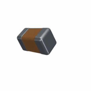
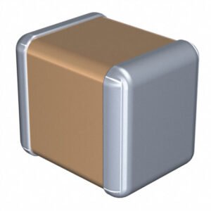
TDK’s C1005x8R1E103M050BA is a commercial-grade multilayer ceramic chip capacitor (MLCC) in the ultra-compact 0402 (1005 metric) size, delivering a nominal capacitance of 10,000 pF (10 nF), 25 VDC rated voltage, X8R temperature characteristic, and ±20% tolerance. It is built for general-purpose use in spaces exposed to elevated ambient or self-heating—power modules, RF front-ends, compact DC/DC converters, and logic rails—where a small, thermally robust bypass/decoupling capacitor is required.
As part of TDK’s “C series – high temperature application” MLCC family, this device supports a maximum operating temperature of +150 °C with a guaranteed operating range from −55 °C to +150 °C. The C series is offered in the familiar JIS/EIA size codes (0402 through 2220) and uses a simple, monolithic construction with Cu/Ni/Sn terminations for mechanical strength and reliability. (See the series overview and structure on page 3, which specify the −55~+150 °C range and depict the internal stacked-dielectric/termination system. )
The exact catalog part “C1005x8R1E103M050BA” decodes as:
-
C1005 = 1.00 × 0.50 mm body (0402),
-
X8R = ±15% characteristic over −55~+150 °C,
-
1E = 25 VDC rating,
-
103 = 10,000 pF (10 nF),
-
M = ±20% tolerance,
-
050 = nominal thickness 0.50 mm,
-
BA = internal packaging/code.
(Page 4 explains TDK’s catalog number construction including size, dielectric code, voltage code “1E=25V,” tolerance “M=±20%,” and thickness code tables. )
Within the C1005 high-temperature matrix, TDK lists 10 nF X8R options at 25 V with both K (±10%) and M (±20%) tolerances; this specific “M050BA” variant corresponds to the ±20% option. (See the X8R capacitance range table for 0402 on page 14 showing “C1005X8R1E103M050BA.” )
3 small highlights
-
150 °C capable X8R: Stable operation from −55 °C to +150 °C for hot-spot placements.
-
Ultra-compact 0402: 1.00 × 0.50 mm footprint with 0.50 mm nominal thickness for dense layouts.
-
Proven C-series platform: Monolithic MLCC construction with Cu/Ni/Sn terminations for reliability in reflowed SMT assemblies.
Specifications — TDK C1005x8R1E103M050BA
| Parameter | Value |
|---|---|
| Manufacturer / Series | TDK, C series (Commercial grade, high-temperature application). |
| Part number | C1005x8R1E103M050BA (0402 MLCC; 10 nF). |
| Capacitance | 10,000 pF (10 nF) |
| Capacitance code | 103 (10 × 10³ pF). |
| Tolerance | ±20% (M). |
| Dielectric / Temp characteristic | X8R (ΔC/C within ±15% from −55 °C to +150 °C). X8R characteristic and temperature range defined on page 4; C-series max operating temp stated on page 3. |
| Rated voltage (DC) | 25 V (code 1E). |
| Operating temperature | −55 °C to +150 °C |
| Package / Case | 0402 (JIS 1005 metric). |
| Size (L × W) | 1.00 mm × 0.50 mm typical. |
| Nominal thickness | 0.50 mm (code 050). |
| Max seated height | Typically ≤ 0.55 mm in 0402 builds (designers often treat as max height target based on nominal 0.50 mm thickness + tolerance). |
| Termination | Cu/Ni/Sn plated terminations shown in the product structure diagram. |
| Mounting | Surface Mount (reflow). |
| Application class | Commercial grade. |
| RoHS / Halogen | RoHS & halogen-free. |
| Typical functions | Decoupling, smoothing, snubber/resonant circuits in high-temperature environments; peripherals near IGBT/SiC/GaN devices |
| Part-number decoding | Per page 4 catalog number construction (size, dielectric, voltage, capacitance, tolerance, thickness, packaging). |
Note on availability within the C1005/X8R/25 V/10 nF slot: TDK lists both ±10% (K) and ±20% (M) tolerance variants; C1005X8R1E103M050BA corresponds to the ±20% version.
Applications — where this part fits best
-
Hot-zone decoupling in compact electronics: Place directly at IC supply pins (MCUs, ASICs, RF transceivers) in dense, thermally constrained boards where local ambient can approach 125–150 °C. The 0402 footprint keeps loop inductance low; the 25 V rating covers numerous 1.0–12 V rails with margin.
-
Power conversion snubbers & damping networks: For small RC snubbers or frequency-shaping elements around switch nodes in buck/boost modules or POL regulators. The X8R dielectric’s high-temperature tolerance helps maintain predictable behavior close to MOSFETs or coils.
-
Gate-drive & wide-bandgap periphery: Peripheral filtering and edge-shaping in IGBT/SiC/GaN drive stages, where heat from power devices elevates local temperature. (C-series “APPLICATION” mentions peripheral circuits of IGBT/SiC/GaN devices)
-
Signal integrity cleanup: As high-frequency shunts or EMI bypass elements on high-speed lines, clocks, or sensitive analog nodes—especially when those nodes are near heat sources.
Design & handling notes (practical guidance)
-
DC-bias behavior: As with all Class-II dielectrics, effective capacitance will decrease under applied DC bias. When the design is bias-sensitive (e.g., ultra-tight pole locations), consider margining the nominal value or using multiple capacitors in parallel to recover effective C at operating bias.
-
Thermal headroom: While rated for +150 °C operation, the most robust designs keep some margin to account for localized self-heating from adjacent components. Follow TDK’s derating guidance whenever product temperature approaches the top end of the range. (The catalog includes voltage/temperature derating guidance for high-temp dielectrics; see page 16 for the derating figure and X8L example. )
-
Footprint & assembly: Use standard 0402 pads and a symmetric land pattern to minimize tombstoning. Reflow with a temperature profile suitable for small MLCCs and ensure board warpage control to avoid mechanical stress after solder solidification.
-
Mechanical stress: Avoid flexing the PCB near the device; for the smallest sizes, pad design, solder fillet control, and careful depanelization significantly reduce risk of cracking.
Why choose C1005x8R1E103M050BA?
-
Confidence at 150 °C: The C-series target high-temperature conditions while staying commercial-grade and RoHS/halogen free. (Series overview & compliance icons on page 3. )
-
Exact value where you need it: 10 nF at 25 V hits the sweet spot for many local bypass and RC tasks, with ±20% tolerance that’s more than adequate for decoupling and damping.
-
Zero-compromise size: 0402 enables shortest current loops and the highest placement density, improving high-frequency decoupling effectiveness.
At-a-glance (quick facts)
-
Capacitance / code: 10 nF / 103
-
Voltage / dielectric: 25 V / X8R (±15% over −55~+150 °C)
-
Tolerance / thickness: ±20% (M) / 0.50 mm nominal
-
Case size: 0402 (1.00 × 0.50 mm)
-
Operating temp: −55 to +150 °C
-
Mounting / finish: SMT / Cu–Ni–Sn terminations
According to TDK’s Commercial grade, high temperature application – C series catalog, the C1005 package dimensions, temperature capability, catalog-number construction, and the presence of the C1005X8R1E103M050BA listing for 10 nF/25 V are all explicitly documented.
Use this capacitor as your go-to 0402 decoupler in hot zones, small snubbers/dampers in power conversion, or general high-temperature signal conditioning up to 25 V. For designs pushing towards the +150 °C ceiling, follow TDK’s derating guidance and layout best practices to maximize reliability. (Series usage notes and derating guidance appear throughout the C-series catalog)
Specification: TDK C1005x8R1E103M050BA MLCC – 10nF 25V X8R (0402)
|
User Reviews
Only logged in customers who have purchased this product may leave a review.
Related Products

There are no reviews yet.