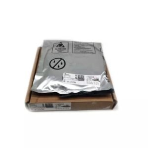
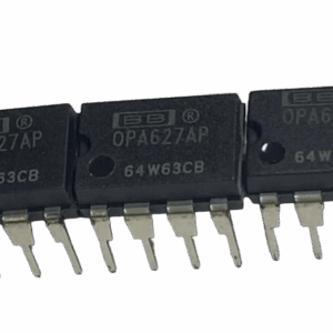
INA121P TI INA121P FET-Input Low-Power Instrumentation Amplifier
- Ultra-Low Bias Current: ±4pA enables direct interface with piezoelectric and capacitive sensors.
- Wide Gain Range: Adjustable from 1V/V to 10,000V/V with ±0.001% nonlinearity error.
- Robust Protection: Withstands ±40V input overload without external components.
Texas Instruments INA121P Instrumentation Amplifier – Precision Signal Conditioning for High-Impedance Applications
The INA121P from Texas Instruments is a high-precision instrumentation amplifier designed for applications demanding exceptional accuracy with ultra-low power consumption. Featuring a FET-input stage, this amplifier delivers industry-leading ±4pA input bias current, making it ideal for interfacing with high-impedance sensors such as strain gauges, RTDs, and pH electrodes.
Built on a 3-op-amp architecture, the INA121P provides:
- Programmable gain (1–10,000V/V) via a single external resistor
- ±40V input protection against voltage transients
- 106dB common-mode rejection ratio (CMRR) at G=100
- Low noise (20nV/√Hz) for sensitive measurements
Packaged in an 8-pin PDIP, it operates across -40°C to +85°C, suitable for industrial, medical, and portable battery-powered systems.
Core Technical Advantages
- Ultra-High Impedance Interface
- The JFET input stage (with >10¹²Ω input impedance) virtually eliminates loading effects when measuring:
- Piezoelectric sensors (vibration/force/pressure)
- Electrochemical cells (pH/ISE probes)
- Capacitive transducers (accelerometers, MEMS)
- Ensures signal fidelity even with source impedances exceeding 1GΩ.
- The JFET input stage (with >10¹²Ω input impedance) virtually eliminates loading effects when measuring:
- Precision DC Performance
- Laser-trimmed offset voltage (±200µV max) minimizes calibration requirements.
- Near-zero drift (±2µV/°C) maintains accuracy across industrial temperatures (-40°C to +85°C).
- 0.001% gain nonlinearity guarantees linear output across dynamic ranges.
- Robust Differential Signal Conditioning
- 106dB CMRR (at G=100) rejects ground loops/noise in harsh environments (e.g., motor drives, industrial PLCs).
- ±40V input overvoltage protection safeguards against transient spikes (IEC 61000-4-5 compliant).
- Flexible Gain & Power Options
- Programmable gain (1–10,000V/V) via single external resistor (RG), supporting:
- Microvolt-level signals (thermocouples: G=100–500)
- High-level outputs (10V bridges: G=1–10)
- Wide supply range (±2.25V to ±18V) enables:
- Battery-powered operation (single 4.5V cell)
- ±15V industrial systems
- Programmable gain (1–10,000V/V) via single external resistor (RG), supporting:
Specifications
| Parameter | Value |
|---|---|
| Supply Voltage Range | ±2.25V to ±18V (4.5V–36V total) |
| Input Offset Voltage | ±200µV (max ±500µV) |
| Input Bias Current | ±4pA (typ) |
| CMRR | 106dB (G=100) |
| Quiescent Current | 450µA (typ) |
| Bandwidth | 600kHz (G=1) |
| Slew Rate | 0.7V/µs |
| Input Noise | 20nV/√Hz @1kHz |
| Operating Temperature | -40°C to +85°C |
| Package | 8-Pin PDIP (7.62mm) |
Applications
| Sector | Use Case | Why INA121P? |
|---|---|---|
| Industrial | Load cell conditioning | 0.001% nonlinearity for metrology-grade scales |
| Medical | ECG front-end | 106dB CMRR cancels 50/60Hz interference |
| Energy | Solar cell IV curve tracing | 4pA bias avoids PV panel loading |
| Automotive | Pressure sensor interface | ±40V protection survives load-dump |
1. Industrial Sensor Conditioning
- Strain Gauge/Bridge Amplification:
- 600kHz bandwidth supports dynamic load measurements.
- 0.001% nonlinearity ensures accurate force/torque monitoring.
- RTD/Thermocouple Interfaces:
- 4pA bias current minimizes self-heating errors.
2. Biomedical Instrumentation
- ECG/EEG Signal Chains:
- 106dB CMRR rejects 50/60Hz power-line interference.
- Respiratory Monitors:
- ±40V protection handles defibrillator surges (IEC 60601 compliant).
3. Portable & Battery-Powered Systems
- Energy Harvesting Sensors:
- 450µA quiescent current extends battery life.
- Capacitive Touch Interfaces:
- FET input prevents signal loading in high-Z circuits.
Design Considerations
- Bias Current Paths: Floating inputs (e.g., thermocouples) require ≥1MΩ return resistors (see Datasheet Fig. 3).
- Thermal Management: PDIP package θJA = 73°C/W – avoid >100mW dissipation in high-Gain configurations.
- Noise Optimization: At G=100, input-referred noise is 20nV/√Hz (dominated by A1/A2 FETs)
Gain Configuration
The gain is set by a single resistor (RG) between pins 1 and 8:
G = 1 + (50kΩ / RG)
Example: For G=500, use RG=100Ω (1% metal film recommended).
Input Protection
- Bias Current Path: Always provide DC return paths for inputs (see Fig. 3 in datasheet).
- Filtering: Add matched RC networks (e.g., R1=R2=1kΩ, C1=C2=100pF) to preserve CMRR.
Low-Voltage Operation
At ±2.25V supplies:
- Ensure input voltages stay within +1.2V to -2.1V of rails.
Package Options & Ordering Information
Below is the complete list of orderable part numbers for the INA121 series, including all package options, pin counts, and shipping formats:
| Orderable Part Number | Package | Pins | Shipping Format | Temperature Range |
|---|---|---|---|---|
| INA121P | 8-Pin PDIP | 8 | Tube (50 pieces) | -40°C to +85°C |
| INA121P.A | 8-Pin PDIP | 8 | Tube (50 pieces) | -40°C to +85°C |
| INA121PA | 8-Pin PDIP | 8 | Tube (50 pieces) | -40°C to +85°C |
| INA121PA.A | 8-Pin PDIP | 8 | Tube (50 pieces) | -40°C to +85°C |
| INA121U | SO-8 (Surface Mount) | 8 | Tube (75 pieces) | -40°C to +85°C |
| INA121U.A | SO-8 (Surface Mount) | 8 | Tube (75 pieces) | -40°C to +85°C |
| INA121U/2K5 | SO-8 (Surface Mount) | 8 | Tape & Reel (2,500 pieces) | -40°C to +85°C |
| INA121U/2K5.A | SO-8 (Surface Mount) | 8 | Tape & Reel (2,500 pieces) | -40°C to +85°C |
| INA121UA | SO-8 (Surface Mount) | 8 | Tube (75 pieces) | -40°C to +85°C |
| INA121UA.A | SO-8 (Surface Mount) | 8 | Tube (75 pieces) | -40°C to +85°C |
| INA121UA/2K5 | SO-8 (Surface Mount) | 8 | Tape & Reel (2,500 pieces) | -40°C to +85°C |
| INA121UA/2K5.A | SO-8 (Surface Mount) | 8 | Tape & Reel (2,500 pieces) | -40°C to +85°C |
Key Differences Between Models
- Package Type
- DIP (Through-Hole):
- INA121P/PA: 8-Pin PDIP (0.3″ width) for breadboarding or prototyping.
- Bulk tubes contain 50 units.
- SO-8 (Surface Mount):
- INA121U/UA: Suitable for PCB mass production.
- Available in tubes (75 units) or tape & reel (2,500 units) for automated assembly.
- DIP (Through-Hole):
- Suffix Variations
- Part numbers ending in “A” (e.g., INA121PA, INA121UA)
- Identical electrical specs, but may include minor datasheet revisions.
- Part numbers ending in “/2K5” (e.g., INA121U/2K5, INA121UA/2K5)
- High-volume packaging (2,500 units per reel).
- Part numbers ending in “A” (e.g., INA121PA, INA121UA)
- Temperature Grades
- All models support industrial temperature range (-40°C to +85°C).
Recommended Parts for Common Use Cases
| Application | Recommended Part | Why? |
|---|---|---|
| Prototyping/Lab Use | INA121P (PDIP) | Easy to solder, breadboard-friendly |
| Volume Production | INA121U/2K5 (SO-8 Reel) | Automated pick-and-place compatible |
| Medical Devices | INA121UA (SO-8 Tube) | Compact footprint, verified in bioinstrumentation |
Footprint: PDIP (9.81mm x 6.35mm x 4.57mm).
Why Choose INA121P?
- Precision: Laser-trimmed for low offset (±2µV/°C drift).
- Flexibility: Supports single +5V or dual ±18V supplies.
- Reliability: Industrial-grade temperature range.
Comparison: INA121P vs. INA128
INA121P vs. INA128 Quick Reference
| Parameter | INA121P (FET Input) | INA128 (Bipolar Input) | Winner |
|---|---|---|---|
| Input Bias Current | 4pA (negligible loading) | 1nA (may cause errors) | ✅ INA121P |
| Input Impedance | >1TΩ (near-ideal) | ~1GΩ | ✅ INA121P |
| Voltage Noise | 20nV/√Hz (slightly higher) | 12nV/√Hz (better) | ✅ INA128 |
| Current Noise | 0.0006pA/√Hz (best for high-Z) | 0.4pA/√Hz | ✅ INA121P |
| CMRR (G=100) | 106dB (superior rejection) | 100dB | ✅ INA121P |
| Supply Range | ±2.25V to ±18V | ±1.35V to ±18V (better for low voltage) | ✅ INA128 |
| Quiescent Current | 450μA (low power) | 700μA | ✅ INA121P |
Design Selection Guide
- Choose INA121P when:
- Signal source impedance >10kΩ (pH, piezoelectric, floating sensors).
- Ultra-low bias current is critical (electrochemical cells, bioelectrodes).
- Operating in noisy environments (industrial/medical systems).
- Choose INA128 when:
- Measuring low-impedance signals (<1kΩ, e.g., strain gauges, RTDs).
- Lower voltage noise outweighs bias current needs.
- Designing cost-sensitive, non-critical systems.
Key Insight
- High-Z ≠ High Noise:
For source impedances >10kΩ, INA128’s current noise dominates (e.g., 0.4pA/√Hz × 100kΩ = 40nV/√Hz), making INA121P quieter overall despite its higher voltage noise. - Supply Limitations:
INA128 supports single-supply 3V systems; INA121P requires ≥±2.25V (±4.5V total).
Assuming “lower noise = better” without considering source impedance. For high-Z applications, INA121P’s near-zero current noise is decisive.
Detailed Comparison: INA121P (FET-Input) vs. INA128 (Bipolar-Input)
1. Input Bias Current: The Critical Tradeoff
| Parameter | INA121P (JFET) | INA128 (Bipolar) | Implications |
|---|---|---|---|
| Input Bias Current | ±4pA (typ) | ±1nA (typ) | INA121P has 250× lower bias current |
| Input Impedance | >10¹²Ω | ~10⁹Ω | INA121P virtually eliminates loading errors in high-Z circuits |
Why It Matters:
- High-Z Sensors (pH, piezoelectric):
- With a 1MΩ source impedance, INA128 introduces 1mV offset error (1nA × 1MΩ), while INA121P adds just 4µV.
- Critical for:
- Bioelectric measurements (EEG/ECG electrodes)
- Capacitive touchscreens
- Thermocouples:
- INA128’s bias current can cause self-heating errors in low-mass junctions.
2. Noise Performance: Bipolar vs. FET
| Parameter | INA121P | INA128 | Note |
|---|---|---|---|
| Voltage Noise Density | 20nV/√Hz @1kHz | 12nV/√Hz @1kHz | INA128 is ~1.7× quieter |
| Current Noise Density | 0.0006pA/√Hz | 0.4pA/√Hz | INA121P dominates in high-Z apps |
Noise Analysis:
- Low-Impedance Sources (<1kΩ):
- INA128’s lower voltage noise makes it preferable for:
- Strain gauges (350Ω bridges)
- RTD interfaces (100Ω Pt100)
- INA128’s lower voltage noise makes it preferable for:
- High-Impedance Sources (>10kΩ):
- INA121P’s negligible current noise (0.0006pA/√Hz) prevents noise multiplication:
- At 100kΩ source impedance, INA128’s current noise contributes:
Noise = 0.4pA/√Hz × 100kΩ = 40nV/√Hz (worse than INA121P’s 20nV/√Hz)
- At 100kΩ source impedance, INA128’s current noise contributes:
- INA121P’s negligible current noise (0.0006pA/√Hz) prevents noise multiplication:
3. CMRR & Precision Metrics
| Spec | INA121P | INA128 | Winner |
|---|---|---|---|
| CMRR (G=100) | 106dB | 100dB | INA121P (6dB better) |
| Offset Voltage | ±200µV | ±250µV | INA121P |
| Offset Drift | ±2µV/°C | ±3µV/°C | INA121P |
Design Impact:
- INA121P excels in:
- Medical instrumentation (ECG needs >100dB CMRR)
- Industrial PLCs (long cables induce common-mode noise)
- INA128 may suffice for:
- Consumer electronics (e.g., audio interfaces with moderate CMRR needs)
4. Power & Dynamic Range
| Characteristic | INA121P | INA128 |
|---|---|---|
| Quiescent Current | 450µA | 700µA |
| Supply Range | ±2.25V to ±18V | ±1.35V to ±18V |
| Output Swing | Rail-to-rail* | Rail-to-rail* |
Tradeoffs:
- INA128 tolerates lower single-supply voltage (2.7V), useful for 3V systems.
- INA121P’s lower Iq benefits battery-powered sensors (e.g., wireless strain gauges).
*Within 0.9V of rails (typ)
5. Application-Specific Recommendations
| Use Case | Preferred Part | Reason |
|---|---|---|
| pH/Electrochemical | INA121P | 4pA bias avoids electrode polarization |
| Load Cells (350Ω) | INA128 | Better noise with low-Z bridges |
| EEG Front-End | INA121P | 106dB CMRR rejects 50/60Hz EMI |
| Thermopile Sensors | INA121P | No current-induced offset drift |
Summary: Choosing Between INA121P and INA128
- Pick INA121P if:
- Your source impedance >10kΩ (e.g., piezoelectric, capacitive).
- You need ultra-low bias current or >100dB CMRR.
- Operating with floating sensors (thermocouples).
- Pick INA128 if:
- Measuring low-Z signals (RTDs, strain gauges).
- Lower voltage noise is prioritized over bias current.
- Designing cost-sensitive, non-medical systems.
Specification: TI INA121P FET-Input Low-Power Instrumentation Amplifier
|
User Reviews
Only logged in customers who have purchased this product may leave a review.


There are no reviews yet.